Disassembly / Assembly SpaceStation
3
3- 12 SpaceStation, 1.0 gb
1.0
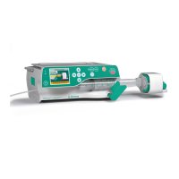
3.8 Interface Board / Module Lock
Designation Ord. No.
Interface board SPS . . . . . . . . . . . . . . . . . . . . . . . . . . . . 3452 1100
with connectors
Connector holder, data, SPS . . . . . . . . . . . . . . . . . . . . . 3452 1160
Module lock SPS. . . . . . . . . . . . . . . . . . . . . . . . . . . . . . . 3452 1119
Cover cap, screws, insulating washers, O-rings
(see „Service Parts and Screw Kit“ ➨ S. 3 - 2)
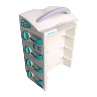
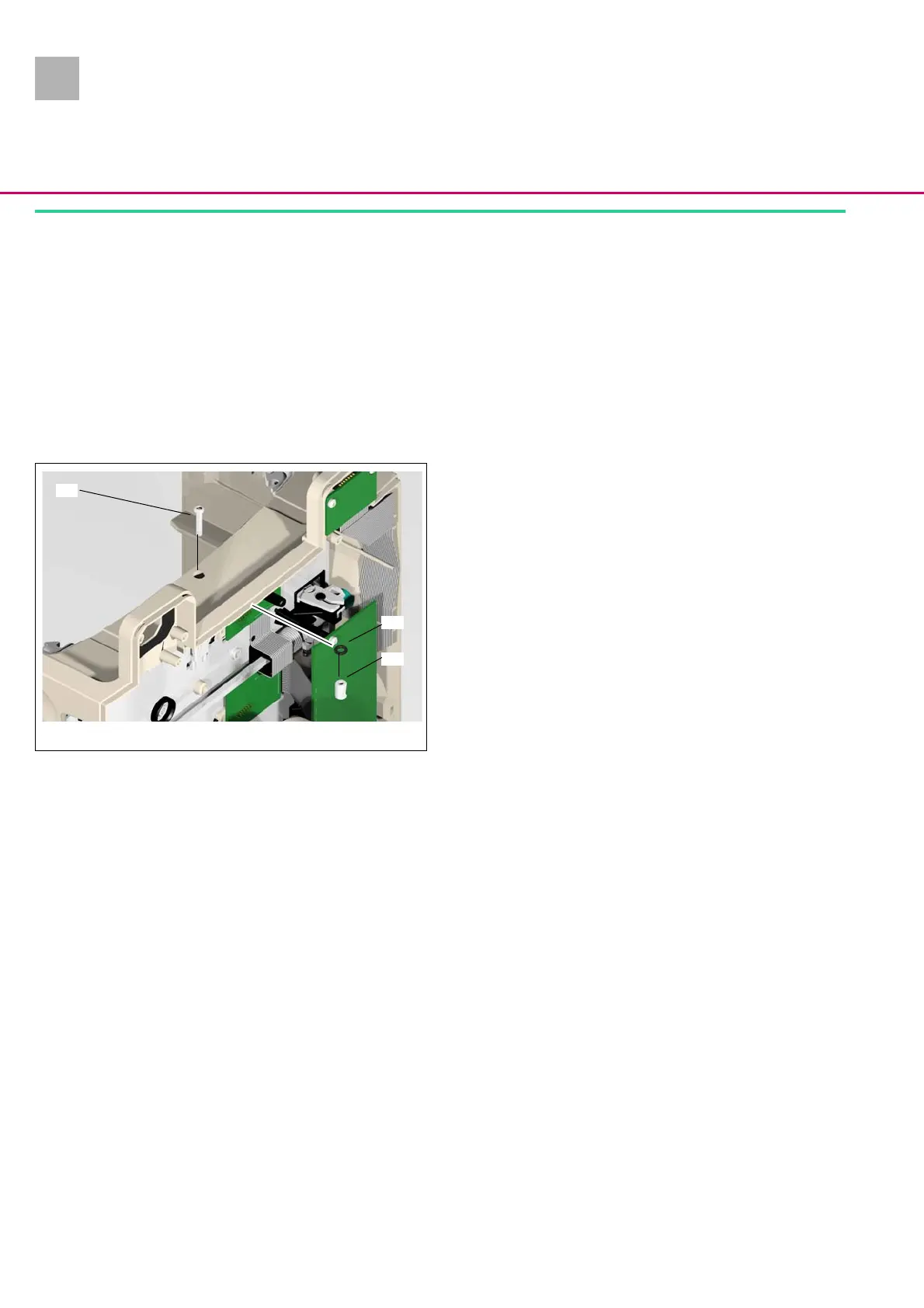
Disassembly
1. Move the lock towards the SpaceCover or another SpaceSta-
tion in the closed position.
2. Loosen one screw (Abb.: 3 - 12 / Item 1) of the module lock
and remove it out of the housing.
3. Pull the module lock sleeve (Abb.: 3 - 12 / Item 3) out of the
housing.
4. Check the O-ring (Abb.: 3 - 12 / Item 2) for damage, and re-
move it out of the housing if necessary.
Abb.: 3 - 12
Legende zu Abb. 3 - 12:
ItemDesignation
1 Module lock screw
2 O-Ring 6.07 x x1.78
3 Module lock sleeve
1
2
3