System Overview
1
1- 2 SpaceStation, 2.0 gb
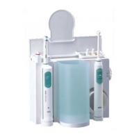
Physical construction
SpaceStation without SpaceCom
The SpaceStation consists of the housing and the housing back
panel.
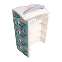
The power supply with power connector and power socket for an-
other SpaceStation is installed on the right side in the housing.
The pumps in the SpaceStation are locked by 8 locking claws
which are built in the housing as subsystem “module locking”. This
subsystem also contains the locking for a SpaceCover or another
SpaceStation.
The pump is released with a release button on the left side of the
housing.
The pumps are connected to the system via the connectors “F2A“
to “F2D“ (from top to bottom) which are integrated in the inter-
face board, while the SpaceStation is connected to other modules
via the connectors “F3“, “F4” and “F5”. The interface board with
connectors is installed on the left side in the housing.
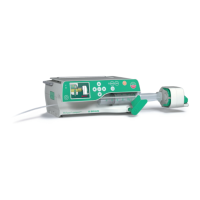
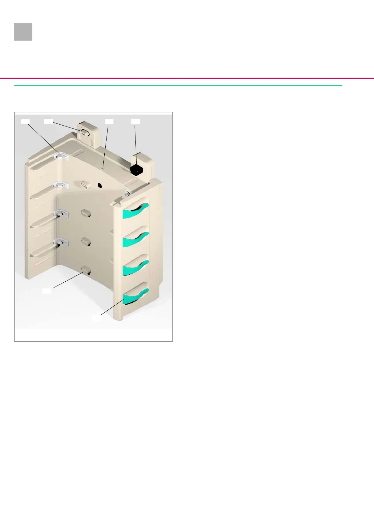
Abb.: 1 - 2 SpaceStation, front view
Legende zu Abb. 1 - 2:
ItemDesignation
1 Pump lock
2 Connector “F5“
3 Module lock
4 Connector “F1B“ (mains output)
5 Tube guide
6 Connector “F2D“
1 2 4
5
6
3
2.0