60
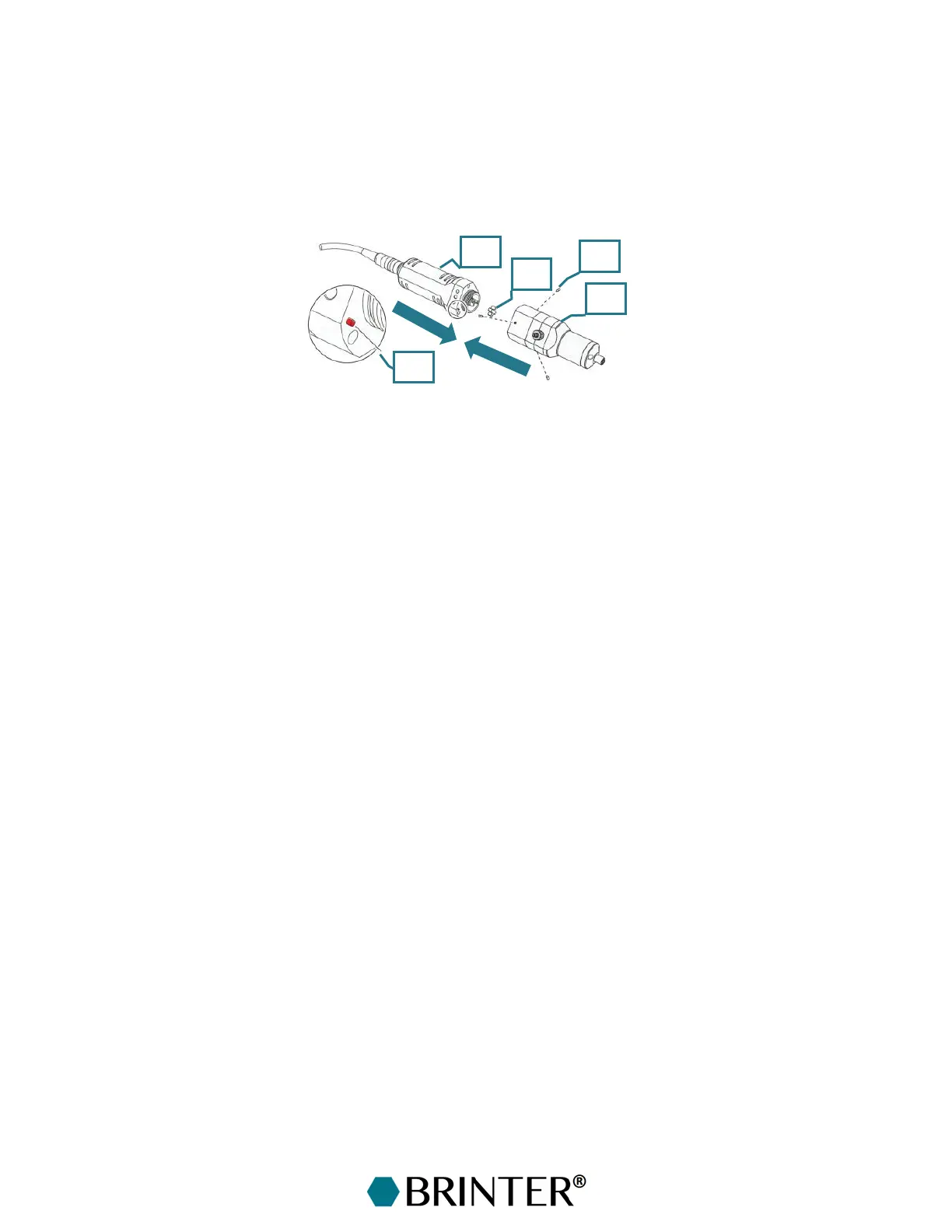
7.2.2 Connecting the Dosing Unit to the Drive Unit
Screw the set of three threaded pins [10] into the thread so that they do not protrude into the coupling
area.
Attach the star-shaped coupling [3] to the coupling of the drive unit [4].
Couple the drive unit [4] to the dosing unit [1] until there is a gap of < 1 mm between the anti-rotation
device [11] and the dosing unit [1].
Set the anti-rotation device [11] to the correct orientation by rotating the dosing unit [1]. Bring the
drive unit [4] and the dosing unit [1] together completely.
Lightly screw in the set of threaded pins [10] to center the drive unit [4] in the correct position.
7.2.3 Supplying and Bleeding the Material
Do not switch on the print head before the printable material has been supplied. Even a brief period
of dry running can damage the stator. Air bubbles in the material to be dosed can cause the material
to spray uncontrollably from the nozzle.
Connect the syringe barrel [12] filled with printable material to the print head material input [13].
Insert a piston inside the syringe barrel to ensure uniform dispensing force and to wipe the syringe
interior clean.
Twist the pressure connector [14] to attach the pressure hose [15] to the syringe barrel [12].
Connect a transparent tube (ID= 4 mm, length 10–20 cm) to the bleed valve [16].
Attach a Luer-Lock needle to the thread [17].