3-84
Confidential
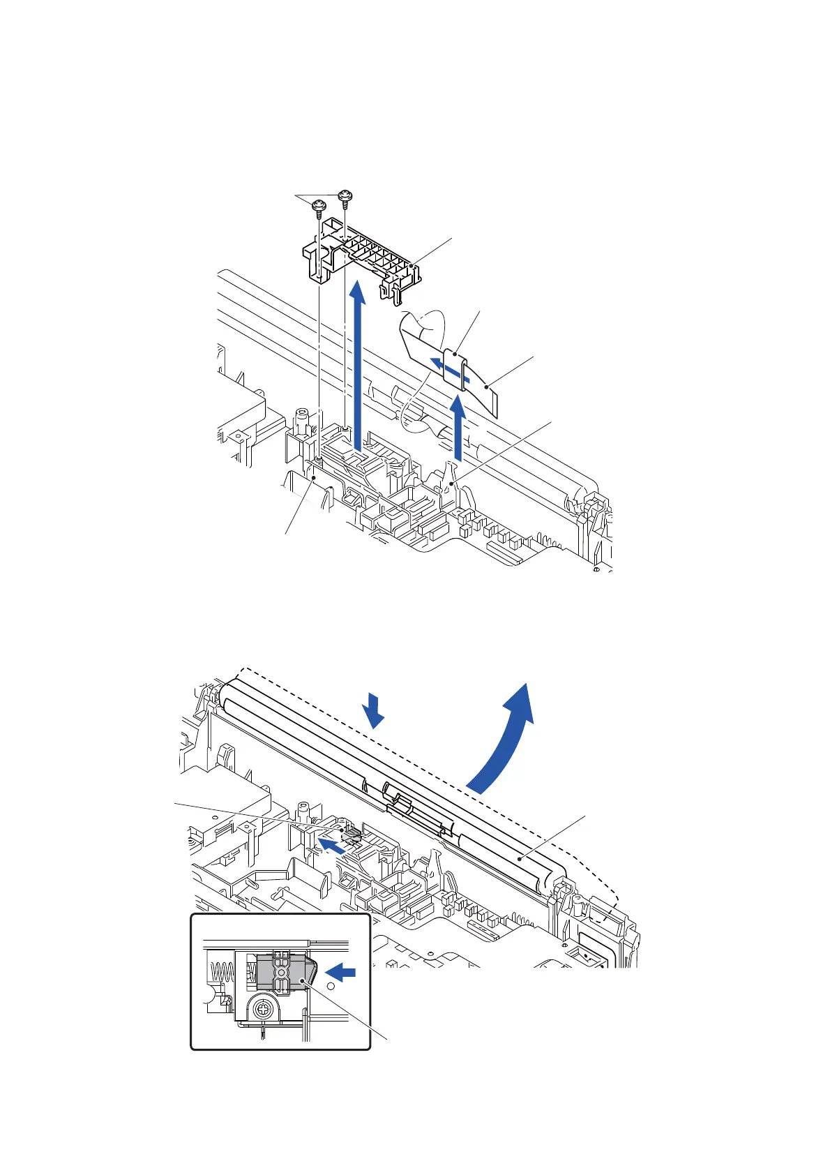
(3) Remove the Flat core from the Lower cover and pull out the Panel flat cable from
the Flat core.
(4) Remove the two screws (TAPTITE CUP B M3x10), release the wiring of the FG
wire TP from the Tilt cover and remove the Tilt cover from the Tilt holder.
Fig. 3-88
(5) Tilt the Control panel ASSY in the direction of the arrow.
(6) Push the Tilt ratch in the direction of the arrow until clicks.
Fig. 3-89
TAPTITE CUP B M3x10
Tilt cover
Flat core
Main PCB harness hold R
Panel flat cable
Tilt holder
3a
3b
4
5
Tilt ratch
Control panel ASSY
6
Tilt ratch
A view
<A view>
6
 Loading...