EasyManuals Logo

BRP Evinrude E-TEC Series User Manual

BRP Evinrude E-TEC Series
443 pages
To Next Page IconTo Next Page
To Previous Page IconTo Previous Page
Page #377 background imageLoading...
Page #377 background image
375
TRIM AND TILT
REMOVAL AND INSTALLATION
13
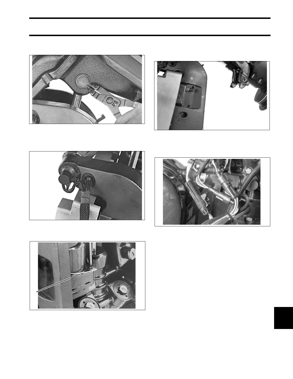
Install external snap rings onto upper pin with
sharp edge facing out.
Place trim/tilt wires in braided tube and install
through hole in the stern bracket.
Attach the ground wire to the trim/tilt unit.
Release the tilt support and lower the outboard.
Torque the manual release valve to 45 to 55 in.
lbs. (5.1 to 6.2 N·m).
Install connector on trim/tilt cable and reconnect
trim connectors to engine wire harness.
Install port lower engine cover. Refer to Power-
head INSTALLATION on p. 262.
25064
25079
1. Ground wire 25057
1
27381
002152

Table of Contents

Other manuals for BRP Evinrude E-TEC Series

Questions and Answers:

Question and Answer IconNeed help?

Do you have a question about the BRP Evinrude E-TEC Series and is the answer not in the manual?

BRP Evinrude E-TEC Series Specifications

General IconGeneral
BrandBRP
ModelEvinrude E-TEC Series
CategoryOutboard Motor
LanguageEnglish

Related product manuals