17
EN
6.2 Connecting the product
with integrated bypass.
NOTE
The following descriptions are based
on the installation and use of the BWT
connection tting.
Read the separate installation instructions for the
warranty in the event of damage.
adjacent diagram while observing the arrows
Connect a corrugated hose to the outlet of the
connection fitting.
water connection IN
(6) with a seal.
Connect the other corrugated hose with a seal
to the product’s outlet water connection OUT (5).
Connect this corrugated hose to the inlet of the
Open the handwheel (bypass) on the connection
leading away
to 6
Connection tting
coming from 5
5
6
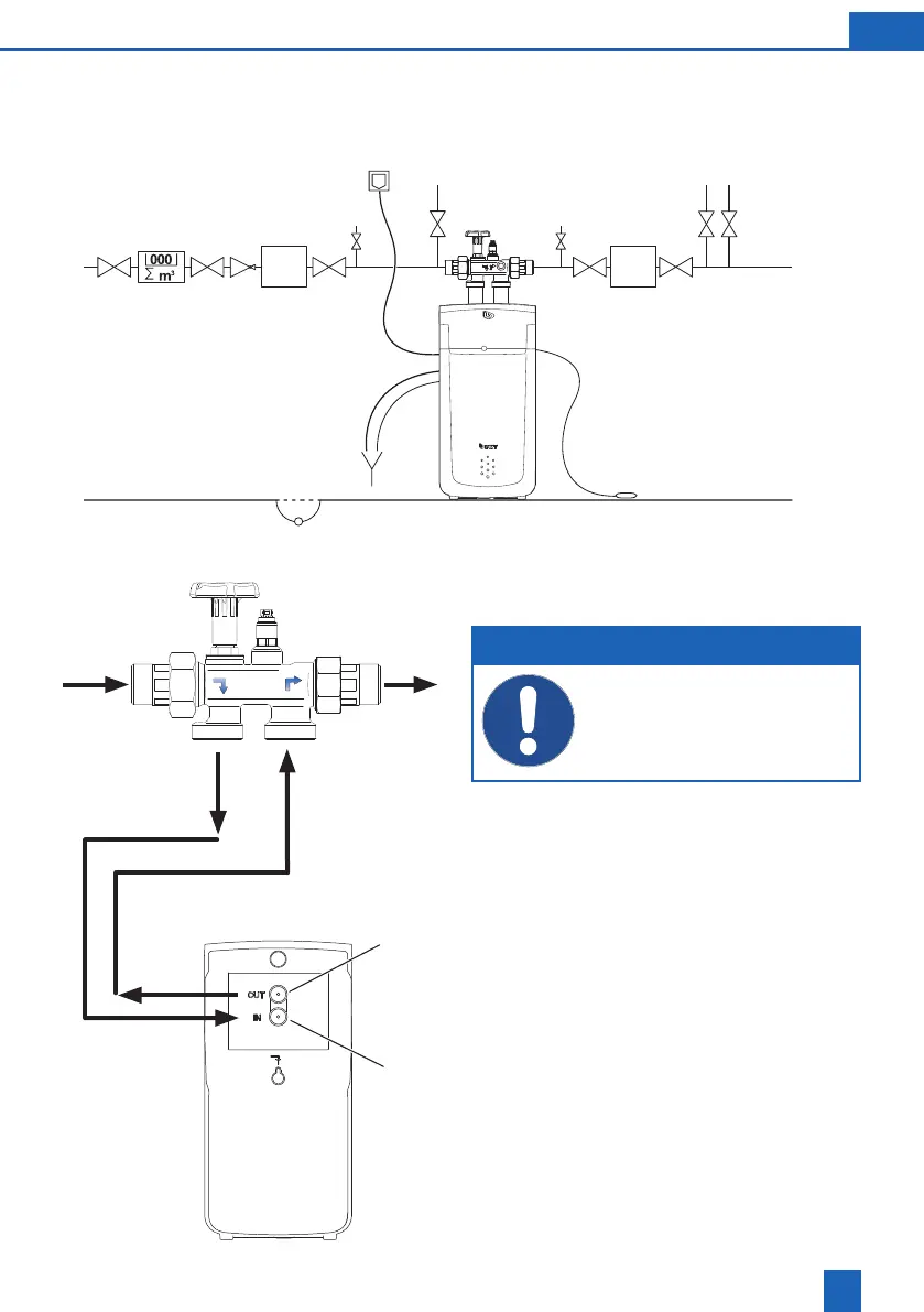
6.1 Installation diagram
(Illustration serves as an example. The individual installation must be adapted to local conditions.)
Pressure reducer, metering unit
may be required depending on
operating conditions
Metering
unit
Garden water pipe, lling
pipe for swimming pool
Cold drinking water,
warm drinking water
Sampling valve Sampling valve
Floor drain
Floor sensor
Filter