CG Drives & Automation, 01-5980-01r2 Functionality 117
The output signal can be programmed as a virtual
connection source and to the relay outputs.
Example:
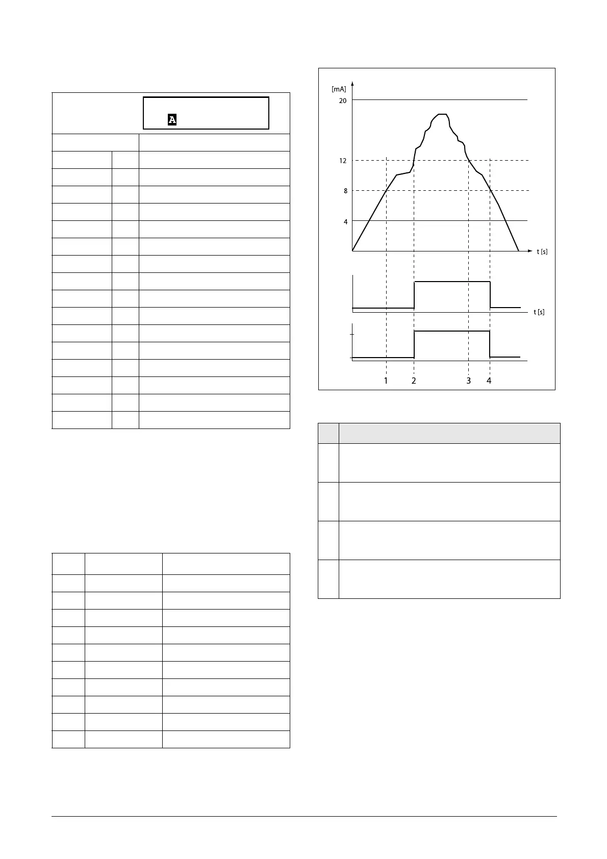
An analogue level sensor with current signal, 4-20 mA, is
connected to the analogue input. See table below.
When the signal on AnIn goes above 60%, the CA output
signal is activated (high), and when the signal on AnIn goes
below 40%, the CA output signal is deactivated (low) again.
The output of CA1 is used as a virtual connection source that
controls the virtual connection destination Run FWD.
Fig. 66
Default: Current
Process Val 0
Torque 1 %
Shaft Power 2 kW
El Power 3 kW
Current 4 A
Heatsink Tmp 5 °C
PT100_1 6 °C
PT100_2 7 °C
PT100_3 8 °C
Energy 9 kWh
Run Time 10 h
Mains Time 11 h
AnIn 12 %
PT100_4 13 °C
PT100_5 14 °C
PT100_6 15 °C
Menu Function Setting
21A Level/Edge Level
511 AnIn Function Process value
512 AnIn Setup 4-20 mA
522 DigIn2 Off
6111 CA1 Value AnIn
6112 CA1 Level HI 60% (12 mA/20 mA x 100%)
6113 CA1 Level LO 40% (8 mA/20 mA x 100%)
6114 CA1 Type Hysteresis
561 VIO 1 Dest Run FWD
562 VIO 1 Source CA1
6111 CA1 Value
Stp Current
No. Description
1
The reference signal passes the Level LO value from
below (positive edge), the comparator CA1 output stays
low, mode = STOP.
2
The reference signal passes the Level HI value from
below (positive edge), the comparator CA1 output is set
high, mode = RUN.
3
The reference signal passes the Level HI value from
above (negative edge), the comparator CA1 output stays
high, mode = RUN.
4
The reference signal passes the Level LO value from
above (negative edge), the comparator CA1 output =
STOP.
t [s]
CA1 Level HI
CA1 Level LO
Signal AnIn
CA1
Mode
RUN
STOP

 Loading...