CHC i83 User Manual 60
Slant reduction error is also a common source of blundered instrument height. The iGx_Download tool makes this
computation automatically for you; however, you must keep track of Slant vs. Vertical and Feet vs. Meters.
Transposition of digits in random heights that occur with tribrachs on tripods is a common source of error.
Measurement to the wrong place on the antenna is a common source of error. Mixing slant measurements in feet with
metric SHMT and radius constants is a common source of error. Confusing slant heights between multiple occupations is
a common source of errors. Using ‘inch’ tapes instead of ‘tenths’ tapes is a common source of errors.
All these errors are eliminated if you use a fixed height 2.0-meter tripod or a 2-meter pole with a Hold-a-Pole for every
static occupation. The answer is always just “2.0” meters. Which is easy to remember.
Rotate your Receiver Correctly
Every antenna has a ‘correct’ rotation. It is VERY important to spin the antenna so that it faces the correct direction.
You can determine the correct rotation for any modeled antenna by looking up the antenna definition on the NGS
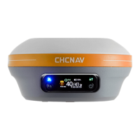
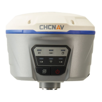
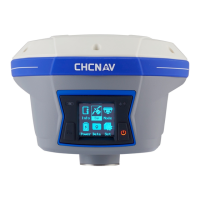
Antenna Calibration website. The i83 receiver should be rotated so that the display points to the north.
North Reference Point (NRP) = Man-Machine Interface (MMI)
What happens if you don’t rotate the antenna correctly? OPUS has a calibration file for every antenna that relates a
change in L1 height offset by the position of the satellite in the sky and the XY offset of the center of the antenna from
the center of the mounting nut.
OPUS compensates for the northing, easting offset assuming the antenna is facing North. If you rotate the antenna 180°
so that the MMI is pointing to the South, then the offset error is doubled, and your final solution will be in error by
double the centering offset!
Bad rotation alignment can also make an occupation appear noisy. OPUS compensates for the antenna vertical offset
changes depending on where satellites are in the sky. If the antenna is mis-rotated, the compensation will be applied
incorrectly.
Use the Correct Antenna Model
Make sure that you have the correct antenna model selected. Some antennas have multiple radomes and revisions
listed.
For example: the Ashtech version of the Dorne Margolin chokering (which is a replacement of ASH700936 which has
even more models and revisions) has 10 revision / dome combinations:
ASH701945B_M NONE
ASH701945B_M SCIT
ASH701945B_M SCIS
ASH701945B_M SNOW
ASH701945C_M OLGA
ASH701945C_M SCIS
ASH701945C_M SNOW
ASH701945C_M SCIT
ASH701945C_M PFAN
ASH701945C_M NONE
Each revision has a different calibration, you must select the correct radomes model, or you will introduce height
uncertainty to your solution.
#12 Why does Modern RTK work where OPUS fails?
Yes, OPUS is substantially more finicky than modern GNSS RTK. OPUS jobs routinely fail in places and at times that RTK
works flawlessly. There are two primary reasons: number of satellites and baseline length.
Number of Satellites and Signals
OPUS is GPS only. Modern GNSS RTK uses additional satellites (GLONASS, Galileo, BeiDou) and additional signals like GPS
L2C, GPS L5 and GLONASS L3.