4-1
6200 Packet-Optical Platform Installation, Commissioning, and Testing Procedures
Release 1.1 009-6200-201 Draft Issue 1
Copyright
©
2014 Ciena
®
Corporation September 2014
Preparing for installation and
commissioning 4-
This chapter provides information useful to prepare an 6200 network element
for installation and commissioning. The topics covered are:
• rack configuration
• power requirements
• tools and material list
Rack configuration
The 6200 network element can be mounted on a variety of telecommunication
equipment racks, including:
• Standard European Telecommunication Standards Institute (ETSI) (19 in.
EIA) rack with a standard 300 x 600 mm footprint.
• Standard Network Equipment Building System (NEBS) 2000 rack with a
standard 300 x 600 mm footprint.
• ANSI (23 in.) equipment rack.
Note: The equipment frame must have 0.5-in. and 1.75-in. mounting
centers to accept the chassis.
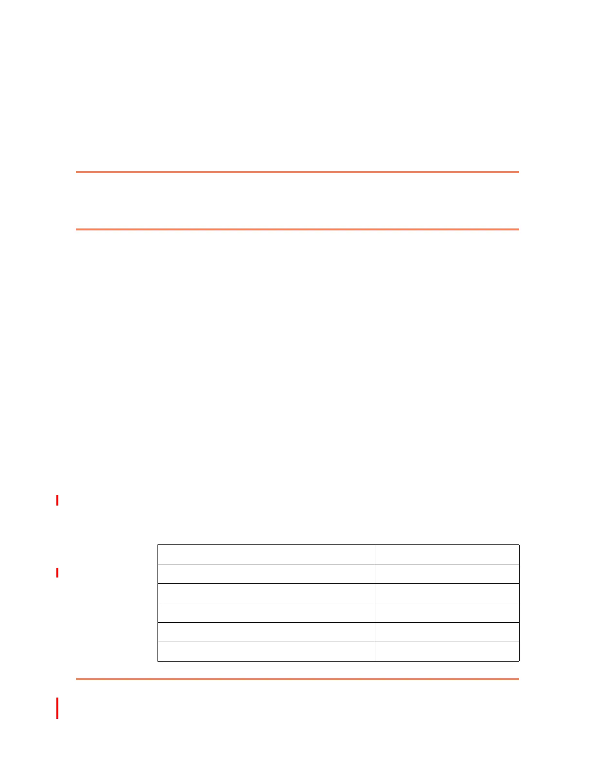
Table 4-1 lists the physical dimensions of the 6200 network element.
Table 4-1
6200 physical dimensions
Specification Description
Basic chassis height 88.5 mm
Expansion chassis height 133 mm
Basic chassis depth 237 mm
Expansion chassis depth 237 mm
Basic chassis width (including mounting flanges) 482 mm
009-6200-201