3 INSTALLATION
3-5
OPERATOR’S MANUAL PRO SERIES
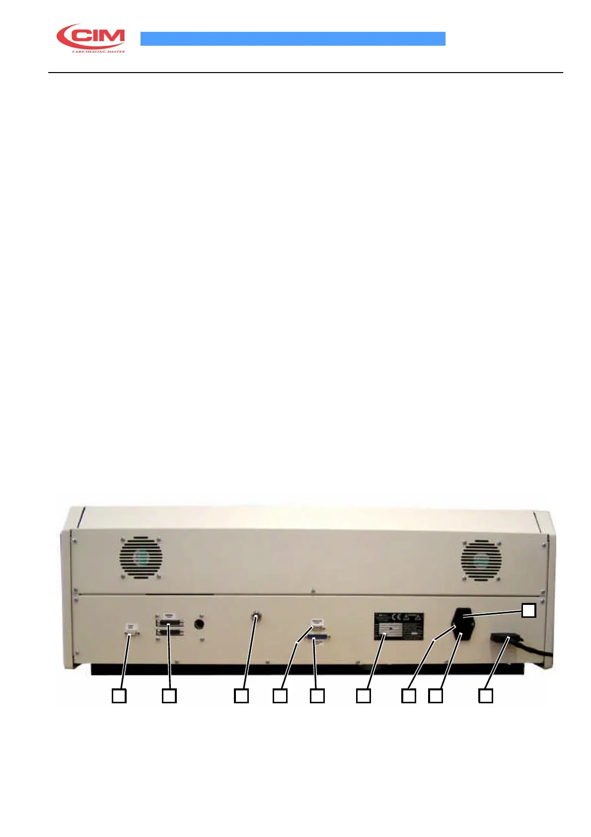
3.3 ELECTRICAL CONNECTIONS C1000
The installation of the machine is easy. Examine the rear control panel of the cover, there are all the sockets for
the various connections as described below:
1.
CHIP CONNECTOR
2.
SERIAL SOCKET FOR PC 25 PIN MALE
3.
KEY SELECTOR (FOR SERVICE USE)
4.
THERMO 1 SERIAL SERVICE PORT
5.THERMO 1 PARALLEL SERVICE PORT
6.
IDENTIFICATIOHN PLATE
7.
FUSE
8.
SOCKET PA 80 FOR MAIN POWER SUPPLY
9.
SOCKET TO CONNECT UNLOADER
10.
MAIN SWITCH
Make the connections as follows:
•
Connect the PC serial cable to socket (2)
•
Connect the parallel cable to socket (5)
•
Connect the unloader connector to socket (9)
•
Connect the power supply cable with PA 80 plug to socket 8)
ATTENTION! TO AVOID ELECTRIC SHOCK THE POWER CARD PROTECTIVE GROUNDING CONDUCTOR
MUST BE CONNECTED TO A GROUND CIRCUIT CONFORMS TO THE NATIONAL STANDARD.
REMEMBER TO CONNECT THE SERIAL CABLE TO THE MACHINE WHILE IT IS SWITCHED OFF TO AVOID
DAMAGING THE CIRCUITS.
10
1 2 3 4 5
6 7 8 9