1-16
Catalyst 6500 Series Switches Installation Guide
OL-5781-04
Chapter 1 Product Overview
Catalyst 6504-E Switch
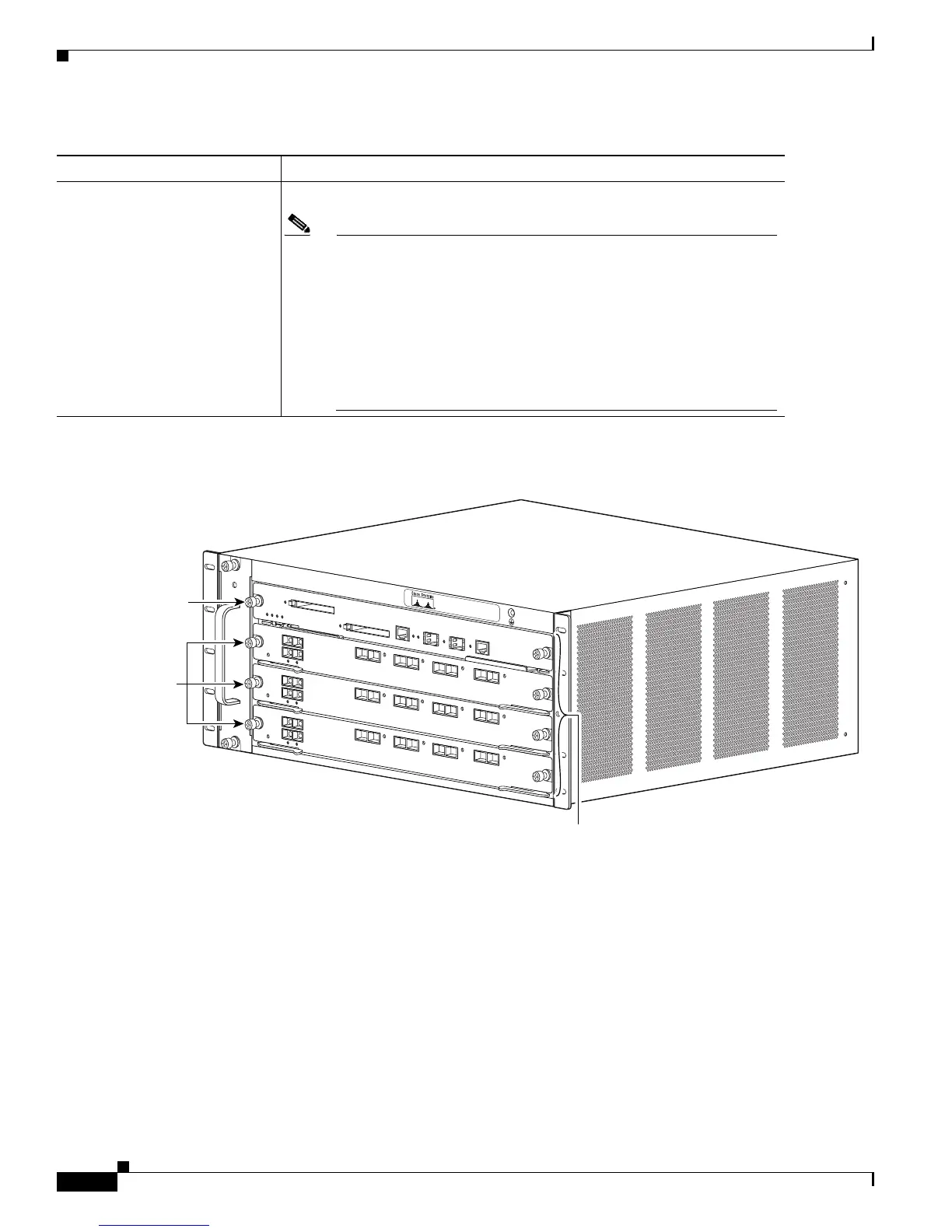
Figure 1-5 Catalyst 6504-E Switch—Front View
Airflow
•
FAN-MOD-4HS—300 CFM
Note To maintain proper air circulation through the Catalyst switch
chassis, we recommend that you maintain a minimum 6-inch
(15 cm) separation between a wall and the chassis air intake or a wall
and the chassis air exhaust. You should also allow a minimum
separation of 12 inches (30.5 cm) between the hot air exhaust on one
chassis and the air intake on another chassis. Failure to maintain
adequate air space can cause the chassis to overheat and the system
to fail. On Catalyst chassis in which the airflow is from front to back,
the chassis may be placed side-by-side.
1. RU = rack units
Table 1-6 Catalyst 6504-E Switch Specifications (continued)
Item Specification
126559
S
T
A
T
U
S
F
AN
S
TA
TU
S
S
T
A
T
U
S
Slots 1-4
(top to bottom)
Supervisor
Engine
OSMs
S
T
A
T
U
S