Lifting and rigging
Page 24 CM6200 Operating Manual
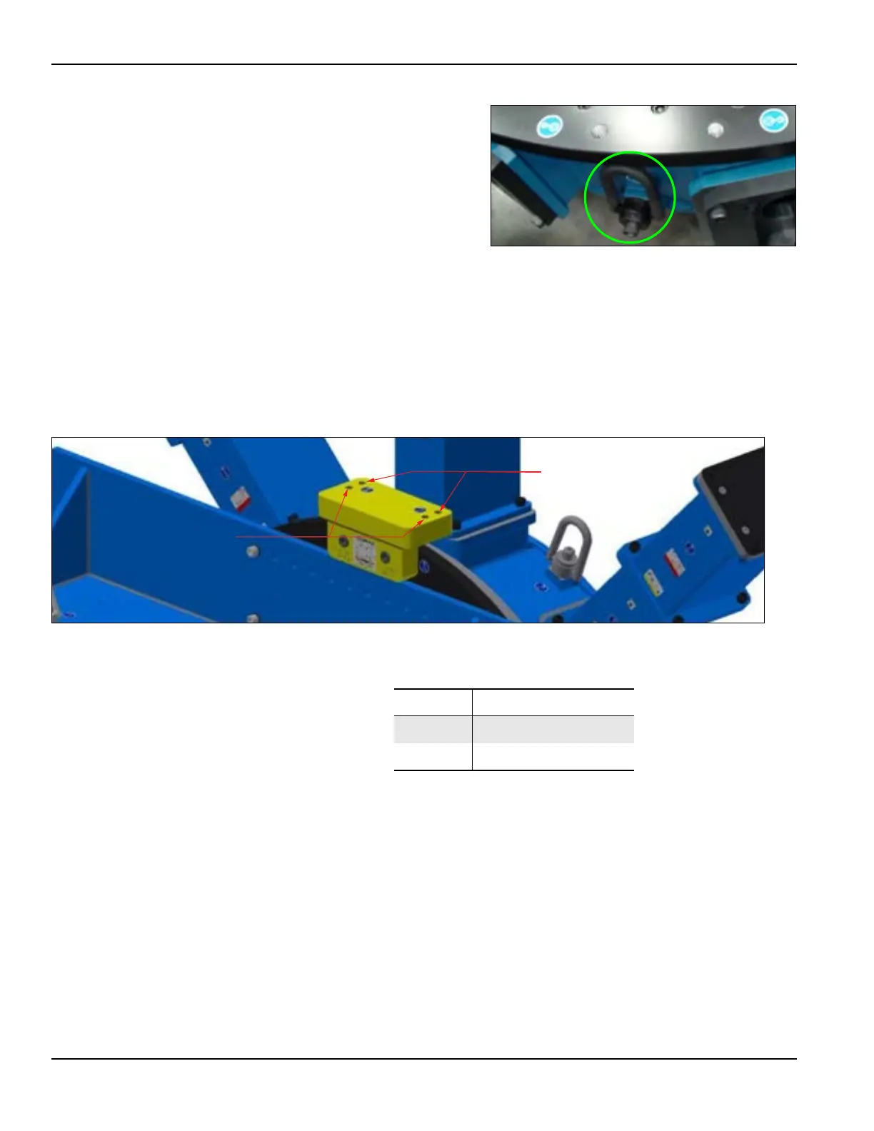
There are four hoist rings locations
on the top of the rotary table (Figure
3-2 on page 23) and eight hoist ring
locations around sides of the hub
(one shown in Figure 3-3). Depend-
ing on the application orientation,
secure the supplied hoist rings in the
necessary locations.
When lifting the machine, pay spe-
cial attention to the location of the
center of gravity. Always make sure
that all machine parts are tightened properly to prevent hazards.
Vertical rigging
The lifting assembly, as shown in Figure 3-4, enables the machine to hang level
with the ID chuck, or to hang level with the OD chuck.
FIGURE 3-4. LIFTING ASSEMBLY ON MACHINE
Install lifting eyes in Position A for ID mounting or in Position B for OD mount-
ing.
Note that only two of these holes are necessary for lifting the machine with lifting
eyes installed. The holes are spaced apart to clear the mounting legs.
The lifting assembly should be torqued to 230 ft-lbs (310 Nm).
FIGURE 3-3. HOIST RINGS FOR LIFTING ASSEMBLED MACHINE
IN VERTICAL POSITION
TABLE 3-1. LIFTING ASSEMBLY IDENTIFICATION
Number Component
1 Position A
2 Position B


 To Next Page