provide a return path for the Mic Bias voltage to ground. Typically, the overall shield
for the Mic 1 high and low side twisted pair can be used for the Mic 1 Bias voltage
return.
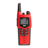
As seen in the image above, the 150Ohm option is selected and the MIC BIAS
ENABLED text is highlighted in a bold black text.
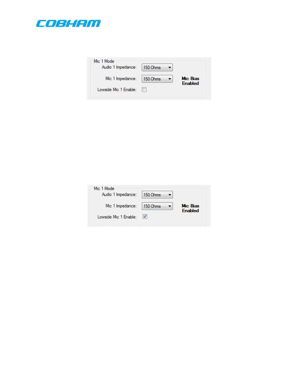
Lowside Mic 1 Enable Setup
When the “MIC MODE_N” discrete input is grounded, pin 76 on the 78-pin connector,
and the Lowside Mic 1 Enable checkbox is checked, grounding the low side of the Mic
1 twisted pair will cause PTT for the transceivers mapped to Mic 1. Discrete PTT_1
(pin 33 of the 78-pin connector) may also be used to initiate transmit in this
configuration.
As seen in the image above, the checkbox for the Lowside MIC 1 Enable is selected.
9.5.1.4 Audio Configuration
Audio and PTT Settings
The Audio and PTT Settings allows the installer to configure the RT-7000 PMR
transceivers to audio input and output channels, and PTT groups. Please note that the
Audio ports and PTTs are all grouped together. MIC/AUD/PTT are all brought together
as a full channel together, commonly referred to as an Audio Port, and are equally
assigned all together. These channels can then be assigned to any Radio the user
desires by selecting the drop down menu and assigning the Radio to the desired Audio
Port.
Default Configuration:
These commodities, technology or software are controlled in accordance with the United States Export Administration Regulations, Export Classification
Control Number (ECCN) EAR99. When exporting, diversion contrary to U.S. law is prohibited.
 Loading...