Hardware
Copyright © 2015 Coda Octopus Products Ltd
39
F180R MOTION Sensor User and Reference Guide
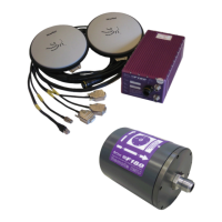
15.Use the information in the table below to make connections between the user
interface cable and the power supply and external equipment including the host PC and
wetpod.
Deutsch AS612–35SA 22–way
Main connector to the <%PRODUCTNAME%>
Box.
Serial RS232 attitude data to receiving
equipment. (COM1)
Serial RS232 RTK/Differential correction
from an external receiver. (COM3)
Serial RS232 navigation data to receiving
equipment. (COM2)
8–way RJ45 100 Base-T plug
Ethernet connection port to host PC
IMU Pod connection, connection on the <%
PRODUCTNAME%> Box side
IMU Pod connection, connection on the IMU
pod side
Supply, supply return and ground
Figure 25: F180R System Connectors Diagram