Hardware
Copyright © 2015 Coda Octopus Products Ltd
40
F180R MOTION Sensor User and Reference Guide
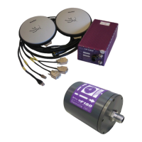
3.3.3 IMU Installation
WARNING: The F180R System IMU contains a number of sensitive and expensive solid
state accelerometer and gyro components. You will cause permanent damage to these
components if you handle the F180R System IMU carelessly. To prevent irreversible
damage, handle the F180R System IMU with great care while you unpack and install
the F180R System IMU.
The F180R System IMUcontains a number of sensitive measuring devices. You must always
take great care when you handle this unit. In particular, be very careful when you place the
F180R System IMU on or mount it to any surface. It is not possible to repair the inertial
measurement components of the F180R System IMU in the field. If you suspect the F180R
System has developed a fault, return it to CodaOctopus for repair.
NOTE: Retain the original packing cases that contain the system during shipment and
use them if you must transport the system from one location to another or if you must
return it to CodaOctopus for any reason. You will invalidate the warranty if you use
improper or inadequate packing to store or transport any part of the system.
Install the F180R System at a suitable location in the vessel:
Installation Orientation
The default installation orientation for the F180R System IMU relative to the vessel is with the
connector end plate (y-axis) pointing to starboard, and the z-axis marked on the unit pointing
down. Please note that the unit can be mounted in any orientation where the exact mounting
orientations are provided in the Configuration Wizard.
NOTE: Definitions of Heading, Pitch and Roll that are output by theF180R System can
be found in Appendix - Rotation Convention.
(See Reference Frame for coordinate conventions)
The IMU should be installed as near as is reasonably practical to the sensor whose motion it
is to monitor. This will minimise the length of any lever arms and ensure that the IMU
motion matches that of the sensor as closely as possible.
The chosen location must provide rigid support so that the IMU does not move relative to
either of the GPS antennas. You do not need to install the IMU at or near the vessel's centre
of rotation. There will be no degradation in performance if you mount the IMU away from
the vessel's centre of rotation.
Special algorithms ensure the IMU will work in any installed orientation with no loss of
performance. They also ensure the system performs well in high vibration environments.
However, you should avoid high vibration environments where possible because these
have additional noise components that will corrupt your measurements. The noise
components are due entirely to the vibration motion and do not arise within the F180R
System system.
If the mounting location for the F180R System IMU is likely to exceed the limits for vibration
and shock listed in the environmental specification, then you should provide special anti–
vibration mounting arrangements. Install the IMU away from strong heat sources. Avoid
subjecting it to rapid changes in temperature, which can degrade the system performance.