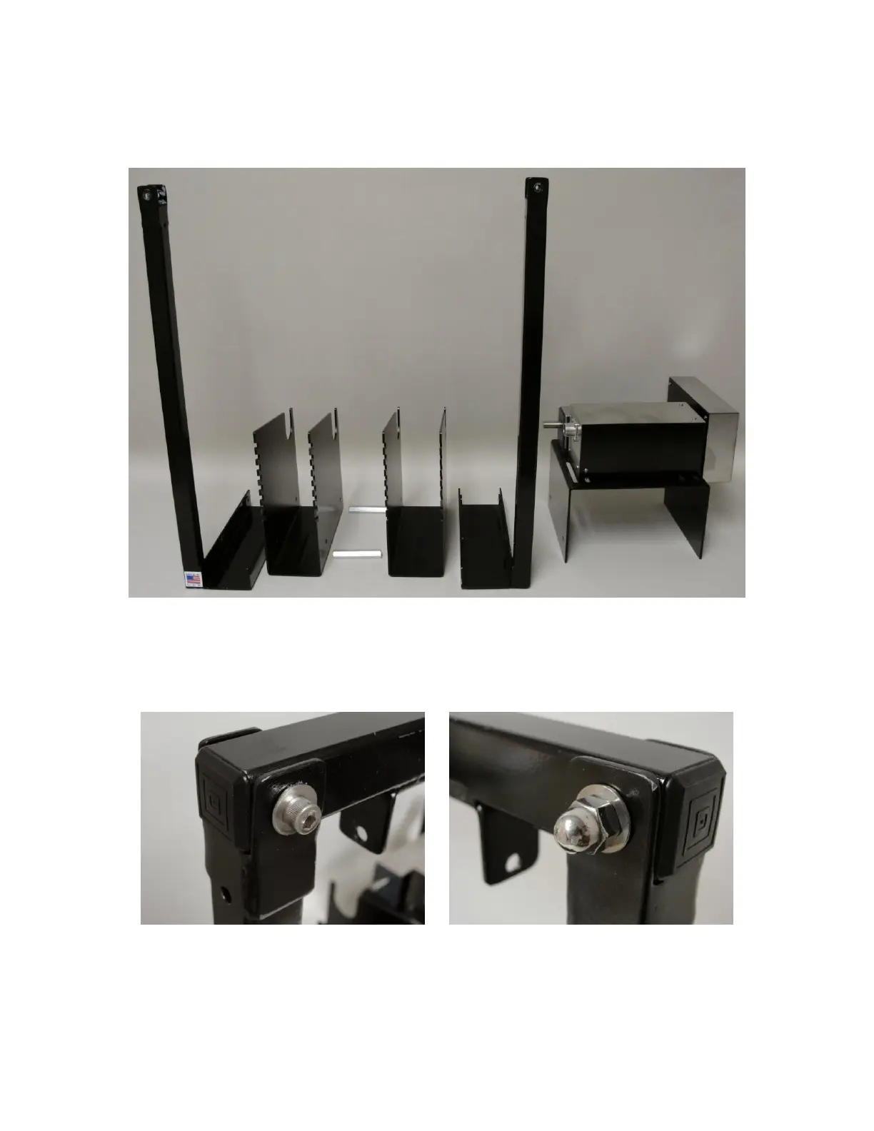
Position the left-support, modular lanes, right-support and motor assembly as shown. The hexagonal
aluminum spacers, which normally connect the motor assembly to the first lane, have been replaced by
the right-support.
Using the 1/4"-20 socket-cap screws, 1/2" long, connect all of the pieces together, but DO NOT fully
tighten. The screws should hold the pieces closely together AND allow them to move.
Attach the top-brace to the supports as shown. Again, DO NOT fully tighten the screws & nuts.
Front View Back View
With all of the components loose and sitting flat on the working surface, begin to fully tighten the
screws, starting with the motor assembly and finishing with the left-support. Then tighten the top-
brace. Be sure that the brace sits flat against the top of the supports.
 Loading...
