LPOD Outdoor Amplifier / Block Up Converter Revision 9
System Connections, Installation and Startup MN-LPOD
2–6
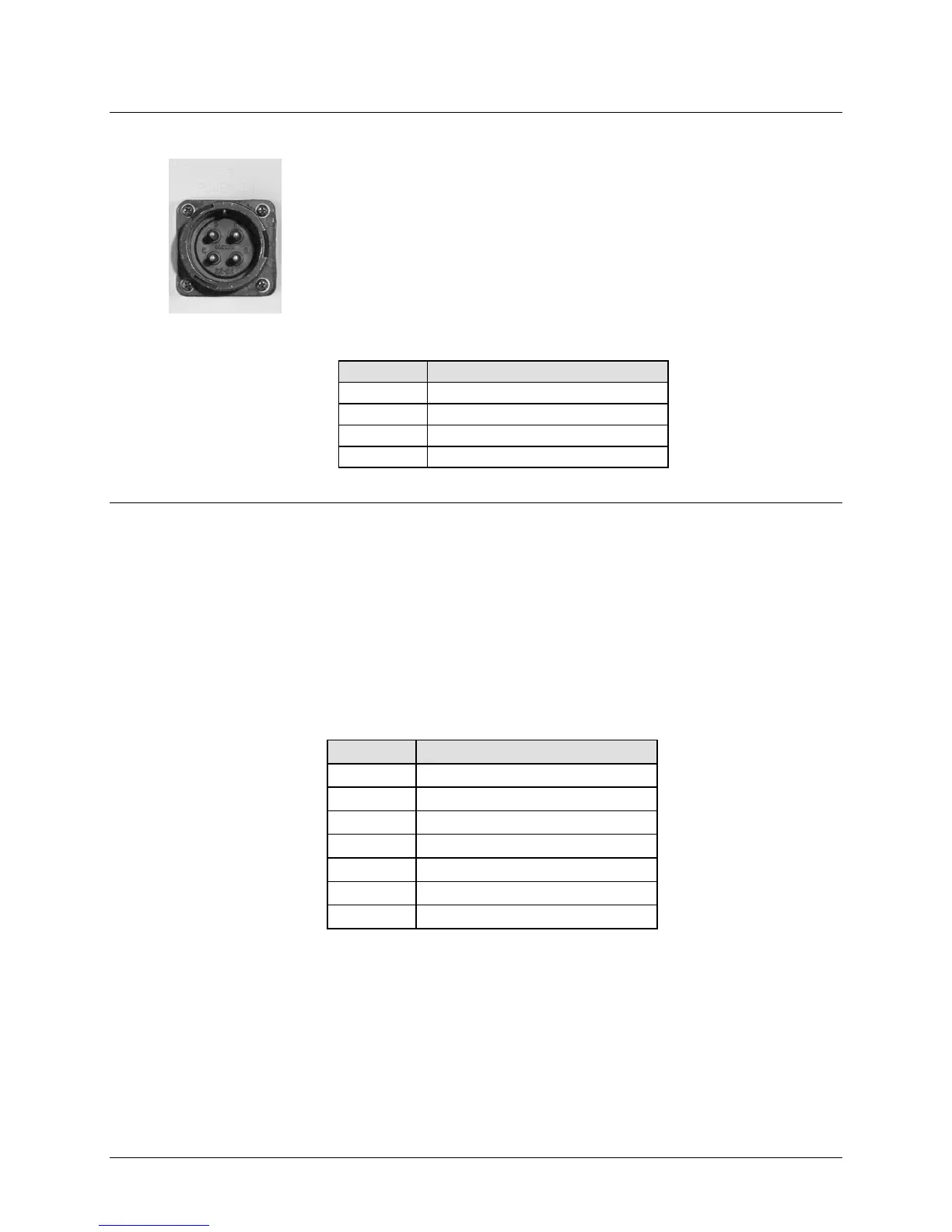
2.2.4.3 LPOD PS 2 ‘J3 | POWER IN’ (DC Power Main)
The mating connector specification and the pin assignments (Table 2-6) unique
to the LPOD PS 2 DC power interface are as follows:
Mating Connector: CEFD P/N CN/CA3106E2222SB (ITT Cannon CA3106E22-
22SB).
Table 2-6. LPOD PS 2 ‘J3 | POWER IN’ Pin Assignments
2.2.4.4 LPOD PS 2 ‘J3 | POWER IN’ 48VDC Power Main Option
The connector type and mating connector specification and the pin assignments (Table 2-7)
unique to the LPOD PS 2 48 VDC power interface option are as follows:
Unit Connector Type: CEFD P/N CN-0000288 (ITT Cannon CA3102E20-15SB-F80A232).
Supplied Mating Connector: CEFD P/N CN-0000289 (ITT Cannon CA3106E20-15SB-F80A232).
Table 2-7. LPOD PS 2 ‘J3 | POWER IN’ 48VDC Pin Assignments
A V+
B V+
C NO CONNECT
D NO CONNECT
E V-
Notes:
1. Use 12 AWG wire to each of the appropriate pins, according to the
individual pin assignments.
2. As an alternative, the ground connection can be made to the unit's
external ground stud.