LPOD Outdoor Amplifier / Block Up Converter Revision 9
System Connections, Installation and Startup MN-LPOD
2–7
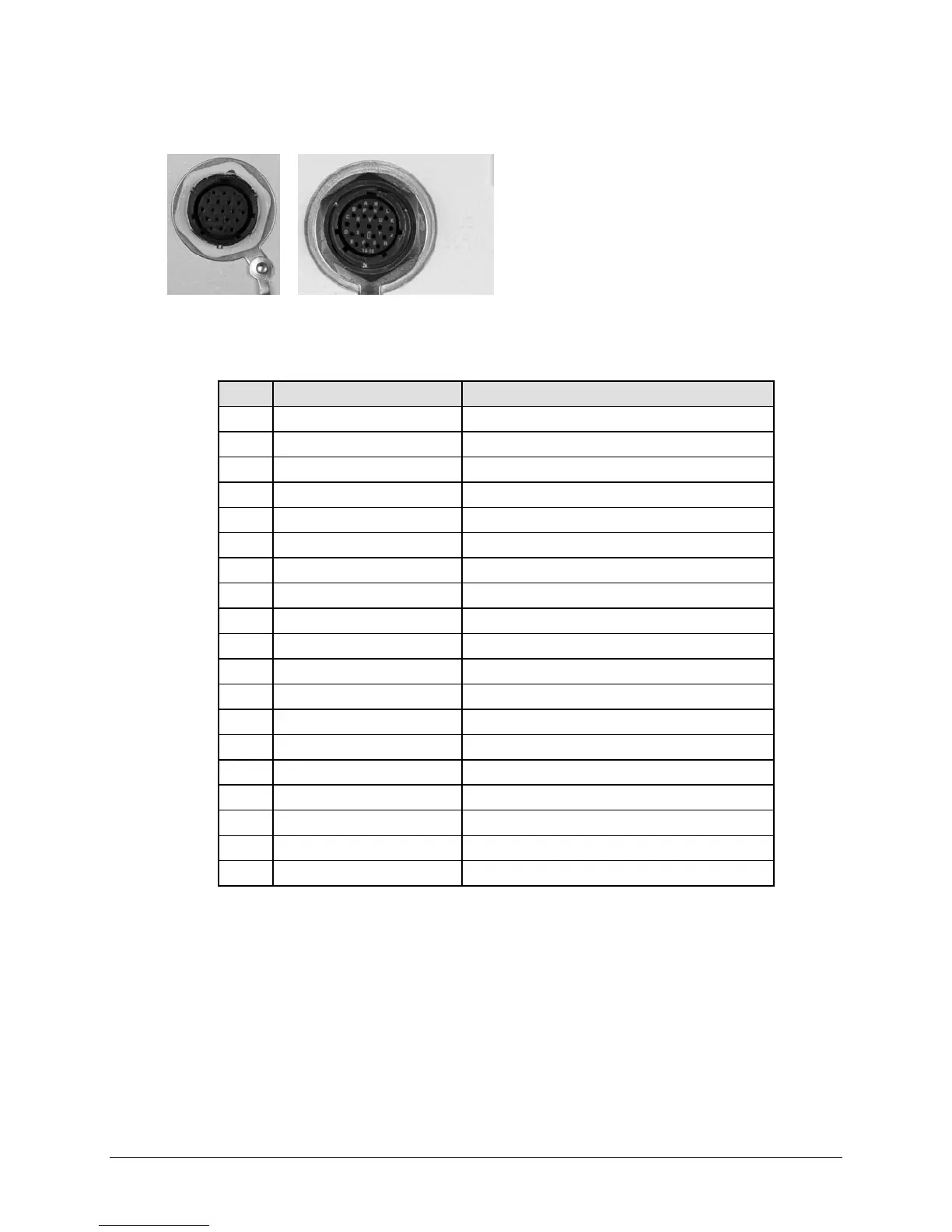
2.2.5 Connector ‘J 6 | COM1’ (Remote Communications and Discrete Control Port)
The ‘J6 | COM 1’ discrete control connector is
the primary input for controlling and
monitoring the LPOD. It is a 19-pin circular
connector, type MS3112E14-19S. The pinout
specification is contained in Table 2-8.
Mating connector: ITT: KPT06J14-19P or
MS3116J14-19P.
Table 2-8. LPOD ‘J6 | COM1’ Pin Assignments
Pin Name Description
A RS485_+RX
B RS485_-RX
C RS485_+TX
D RS485_-TX
E RS232_RD Pin 3 of DB9 female connector
F Ethernet TX+ Pin 3 of RJ45 female connector
G RS232_TD Pin 2 of DB9 female connector
H Ethernet TX- Pin 6 of RJ45 female connector
J TX/RX Switch Drive 1 Pos Not for customer use
K Gnd Ground (also Pin 5 of DB-9F connector)
L SUMFLT In Open when faulted, else +5VDC
M SUMFLT Out When faulted, tied to Pin K, else open
N TX Switch Pos 1 Ind Online/Offline indication
P RX Switch Pos 1 Ind Not for customer use
R +24V Not for customer use
S System Mute Control System muted if customer ties to Pin K
T Switch Common GND reference for Pin N
U Ethernet RX- Pin 2 of RJ45 female connector
V Ethernet RX+ Pin 1 of RJ45 female connector