LPOD Outdoor Amplifier / Block Up Converter Revision 9
System Connections, Installation and Startup MN-LPOD
2–3
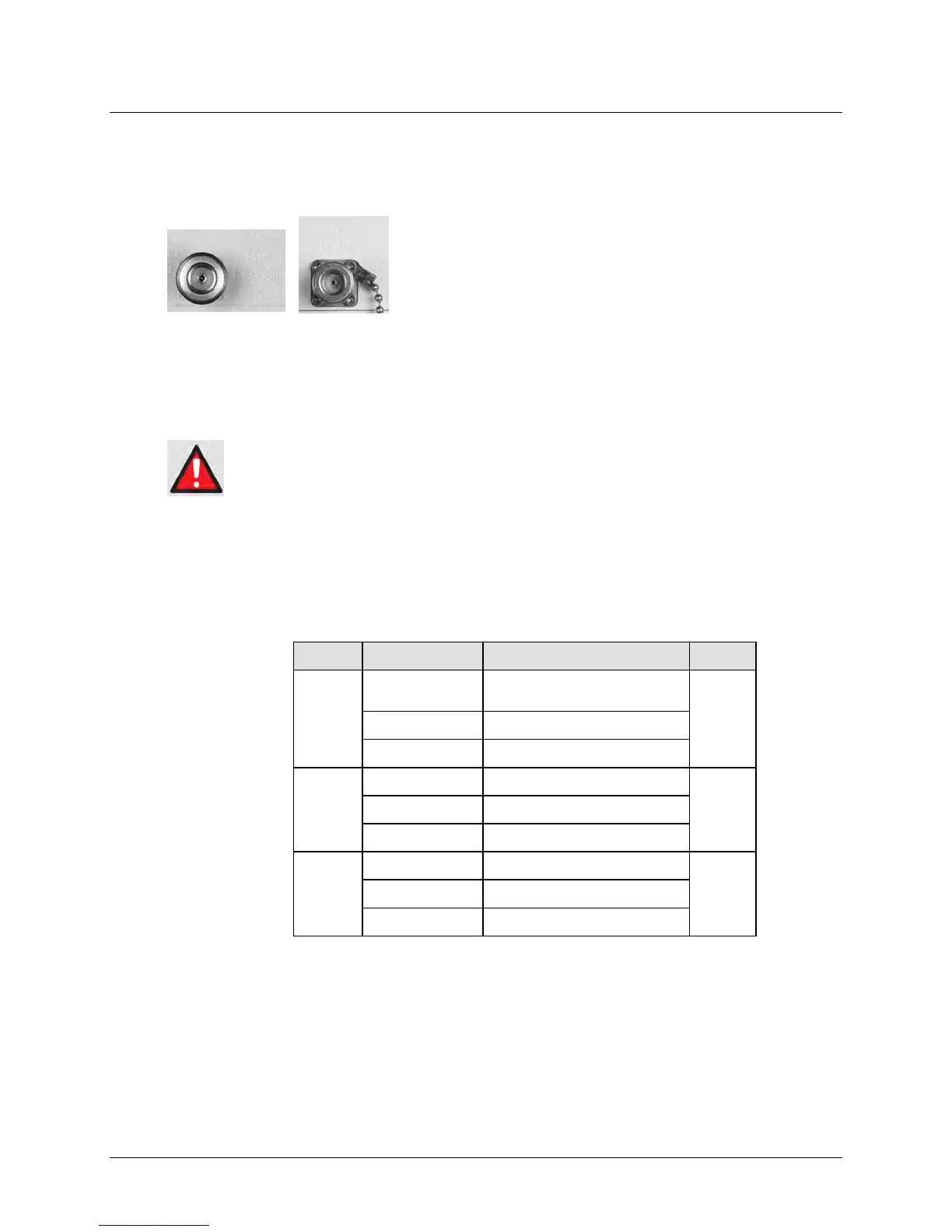
2.2 Interface Connectors
2.2.1 Connector ‘J1 | LBAND IN’ or ‘J1 | Tx IN’
The RF input connector is a Type ‘N’ female connector.
Labeled ‘J1 | LBAND IN’ on the LPOD PS 1 and PS 1.5 models
or ‘J1 | Tx IN’ on the LPOD PS 2 unit, typical input levels (-30
dBm) depend on desired output power and unit attenuation.
To prevent damage to the LPOD, RF input levels should not
exceed +15 dBm.
2.2.2 Connector ‘J2 | RF OUT’
FOR SAFETY REASONS, NEVER LOOK DIRECTLY INTO THE WAVEGUIDE OUTPUT.
The ‘J2 | RF OUT’ connector may be a waveguide or coaxial interface – the type of interface
used depends on the LPOD model and/or frequency range of the unit, as described in Table 2-1
and as shown in Figures 2-1, 2-2, and 2-3.
Table 2-1. ‘J2 | RF OUT’ Interface Type
PS 1
C
Type ‘N’ Female (Standarsd)
CPR137G (Optional)
2-1
PS 1.5
2-2
Ku WR75G (Waveguide)
PS 2
C CPR137G (Waveguide)
2-3 X CPR112G (Waveguide)
Ku WR75G (Waveguide)