Commander SE Advanced User Guide 103
Issue Number: 4
When the second motor map is implemented with parameter 11.45, the display will show the programmed second motor map
values.
There is a delay of approximately 1 second for the digital output to change state when changing from one motor map to the
other.
This parameter is a symmetrical limit on both directions of rotation.
This parameter defines the drive absolute maximum frequency reference, although slip compensation and current limit can
increase the motor frequency further.
Used in unipolar mode to define the drive minimum speed. This can be overridden by maximum speed clamp 21.01. If
adjusted less than 21.02, inactive during jogging.
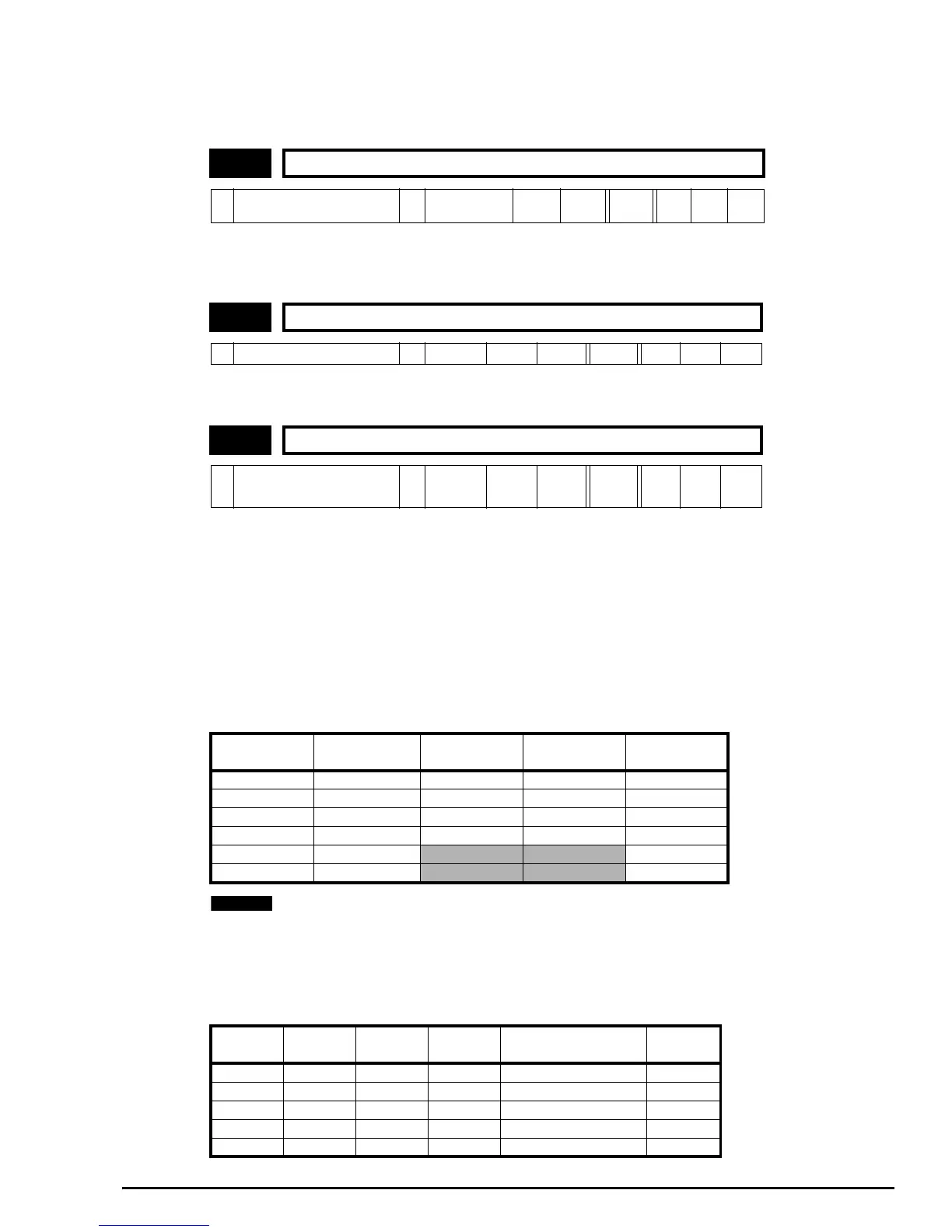
This parameter is used to select a speed reference for motor 2 as follows:
0A1.A2Analog voltage input on terminal 2 and analog current input on terminal 5 selected by terminal 12. Jog
selected by terminal 13.
1A1.PrAnalog voltage input on terminal 2 and three preset speeds selected by terminals 12 and 13.
2A2.PrAnalog current input on terminal 5 and three preset speeds selected by terminals 12 and 13.
3Pr 4 preset speeds selected by terminals 12 and 13.
4PAd Keypad Control.
5PrC Precision reference
Automatic set-up
As parameter 05 is changed from A1.A2 to A1.Pr etc. through the drives keypad, parameter 21.03 will change accordingly as
per the above numerical value.
Also the destination parameters of terminals 12 and 13 will change accordingly as long as 8.39 = 0 - automatic set-up is
enabled.
PrC cannot be selected from parameter 05 through the drives keypad although it will be displayed if parameter 1.14
is set to 5.
Advanced set-up
When 21.03 is set to 0, the reference selected can also depend on the state of bit parameters 1.41 to 1.44. These bits are
controlled by digital inputs such that references can be selected by external control. If any of the bits are set, the appropriate
reference is selected (indicated by 1.49). If more than 1 bit is set the highest number will have priority.
21.01 Motor 2 maximum speed clamp
Ú
0 ~ 1000.0
Ö
Europe> 50.0
USA> 60.0
Hz RW Uni
21.02 Motor 2 minimum speed clamp
Ú
0 ~ 21.01
Ö
0.0 Hz RW Uni
21.03 Motor 2 speed reference selector
Ú
0 ~ 5
Ö
EUR> 0
USA> 4
RW Uni Txt
Parameter 05 Parameter 21.03
Terminal 12
destination
Terminal 13
destination
Parameter 1.49
A1.A2 0 1.41 6.31 1
A1.Pr 1 1.45 1.46 1
A2.Pr 2 1.45 1.46 2
Pr 3 1.45 1.46 3
PAd 4
4
PrC 5
5
Parameter
1.41
Parameter
1.42
Parameter
1.44
Parameter
1.44
Frequency reference
selected
Parameter
1.49
0 0 0 0 Analog reference 1 (A1) 1
1 0 0 0 Analog reference 2 (A2) 2
x 1 0 0 Preset reference (Pr) 3
x x 1 0 Keypad reference (PAd) 4
x x x 1 Precision reference (Prc) 5
NOTE