Commander SE Advanced User Guide 105
Issue Number: 4
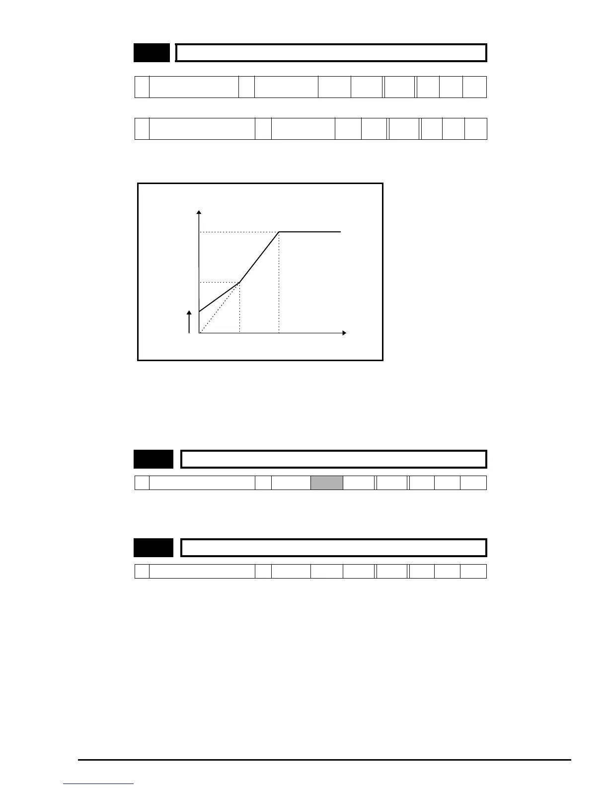
This voltage is used in conjunction with the motor rated frequency (21.06) to define the voltage to frequency characteristic
applied to the machine. If fixed boost is selected (5.14 = 2) the following characteristic is used.
If vector mode is selected (5.14 = 0 or 1) a linear characteristic is used from 0Hz to rated frequency, and then a constant
voltage above rated frequency. When the drive operates between rated frequency/50 and rated frequency/4, full vector based
stator resistance (Rs) compensation is applied. However there is a delay of 0.5s when the drive is enabled during which only
partial vector based compensation is applied to allow the machine flux to build up. When the drive operates between rated
frequency/4 and rated frequency/2 (this may change after some testing has been carried out) the Rs compensation is
gradually reduced to zero as the frequency increases. For the vector modes to operate correctly the stator resistance (21.12),
motor rated power factor (21.10) and voltage offset (21.13) are all required to be set up accurately.
The power factor is used in conjunction with the motor rated current (21.07) to calculate the rated active current. Enter this
from the name plate of the motor. When a rotating autotune is carried out by the drive, the calculated power factor is
automatically saved by the drive.
*Units: poles (by text), pole pairs (by number)
When Auto is selected, the drive automatically calculates the number of motor poles of the machine from the settings in
parameters 21.08 and 21.06. If either of these parameters are adjusted for a special motor or to modify the V/f characteristic,
the automatic calculation may calculate the number of motor poles incorrectly. This would cause an incorrect slip
compensation to be applied and the rpm speed indication would be incorrect. Therefore, the correct number of motor poles
should be programmed manually.
21.09 Motor 2 motor rated voltage
EUR: 50Hz Defaults
Ú
400V units > 0 ~ 480
200V units> 0 ~ 240
Ö
400V units> 400
200V units> 230
VRWUni
USA: 60Hz Defaults
Ú
400V units > 0 ~ 480
200V units > 0 ~ 240
Ö
400V units> 460
200V units 230
VRWUni
21.10 Motor 2 rated power factor
Ú
0 ~ 1.00
Ö
0.85 RW Uni
21.11 Motor 2 number of poles
Ú
Auto, 2P-8P (0-4)
Ö
Auto (0) * RW Uni Txt
voltage
boost
output
voltage
21.09
21.09/2
21.06 / 2 21.06 output
frequency
Output voltage characteristic