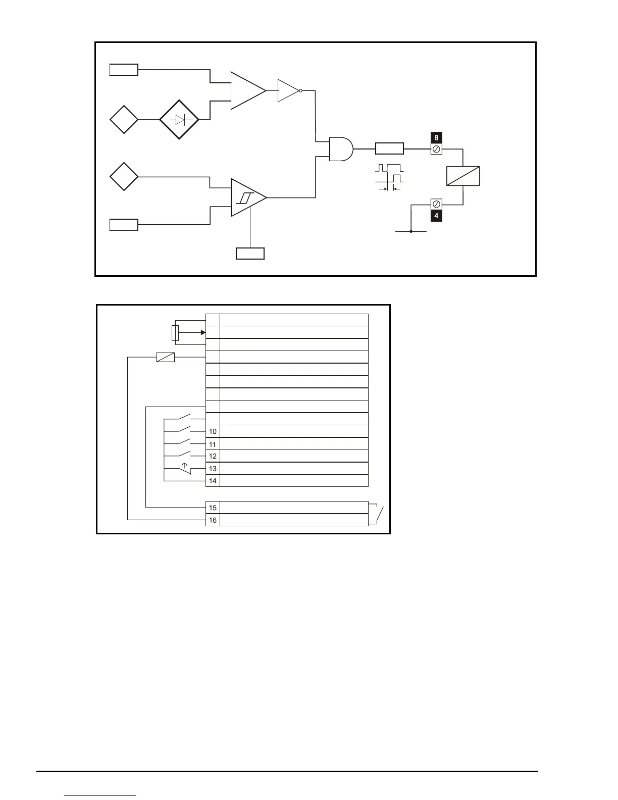
EasyManuals Logo

Control Techniques COMMANDER SE User Manual

Control Techniques COMMANDER SE
195 pages
To Next Page IconTo Next Page
To Previous Page IconTo Previous Page
Page #170 background imageLoading...
Page #170 background image
170 Commander SE Advanced User Guide
Issue Number: 4
Logic diagram
Terminal Set-up (Positive Logic - as default)
2.01
3.05
Zero speed
threshold
Motor
speed
4.01
Motor
current
12.04
Motor current
threshold
+
_
+
_
12.05
H
y
steresis
9.09
Delay
Brake release
relay coil
0V
0V common
Local voltage speed reference input (A1)
+10V reference output
0V common
Remote current speed reference input (A2)
Analog output (motor speed)
+24V output
Digital output
Digital enable / reset
Run forward
Run reverse
Local (A1) / Remote (A2) speed reference
Jog
+24V output
1
2
3
4
5
6
7
8
9
Status relay (Drive healthy)
Q6
K1
K2
T4
Frequency reference
Brake relay coil

Table of Contents

Other manuals for Control Techniques COMMANDER SE

Questions and Answers:

Question and Answer IconNeed help?

Do you have a question about the Control Techniques COMMANDER SE and is the answer not in the manual?

Control Techniques COMMANDER SE Specifications

General IconGeneral
BrandControl Techniques
ModelCOMMANDER SE
CategoryController
LanguageEnglish

Related product manuals