Commander SE Advanced User Guide 27
Issue Number: 4
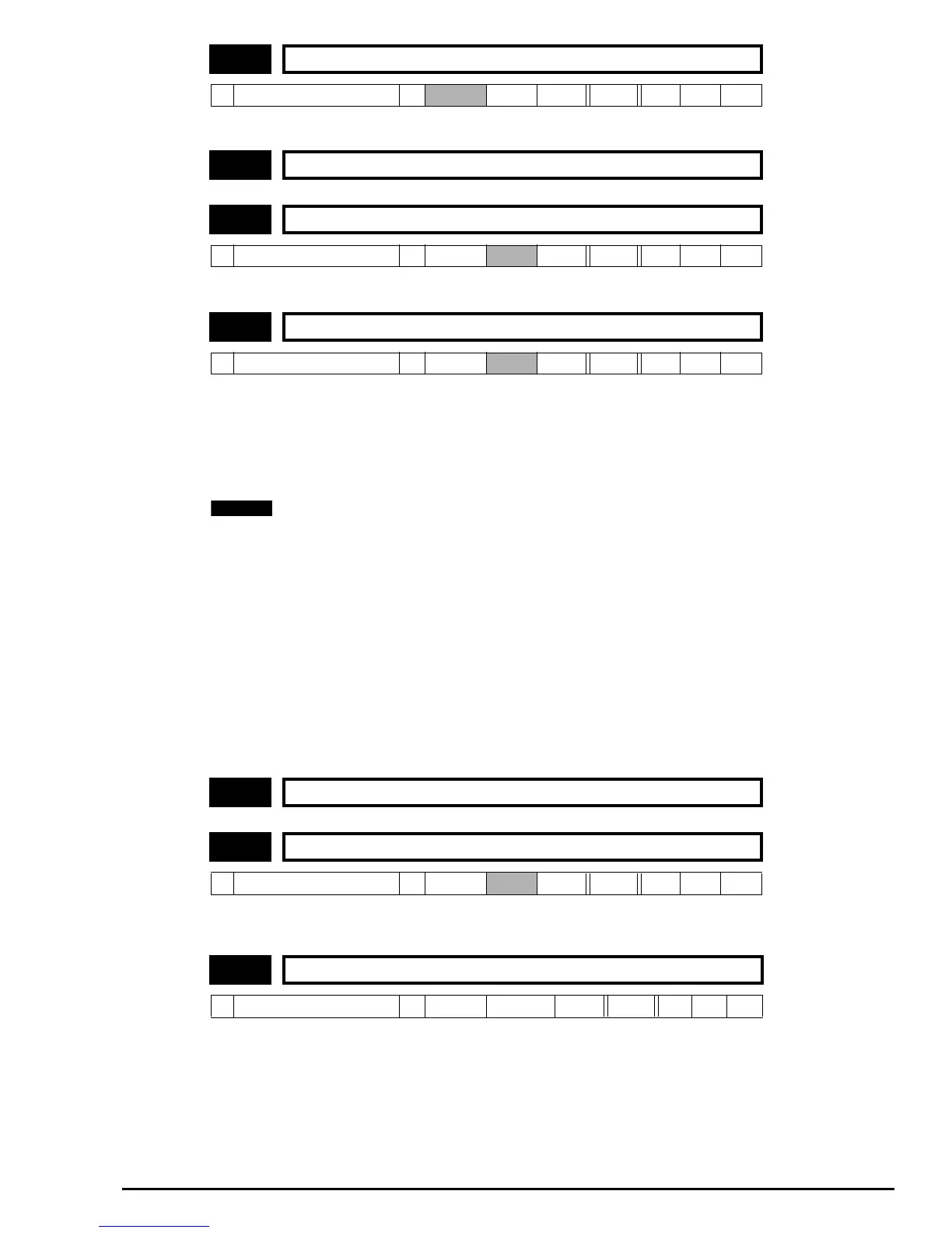
This is the speed reference after the ramps. For analog output scaling, the range of this parameter is ±1.06 or ±21.01.
If this bit is set the ramp will be held.
This parameter has 3 settings as follows:
0 Fast ramp
1 Standard ramp with normal motor voltage
2 Standard ramp with high motor voltage
The acceleration ramp is not affected by the ramp mode, and the ramp output will rise at the programmed acceleration rate
(subject to the current limits programmed). In mode 0 the output of the ramp will also fall at the programmed deceleration rate
(subject to the current limits programmed).
Mode 0 should be selected when using a braking resistor.
In modes 1 & 2 the voltage rising to the standard ramp level (2.08) causes a proportional controller to operate, the output of
which changes the demanded current in the motor. As the controller regulates the DC Bus voltage, the motor deceleration
increases as the speed approaches zero speed. When the motor deceleration rate reaches the programmed deceleration
rate the controller ceases to operate and the drive continues to decelerate at the programmed rate. If the standard ramp
voltage (2.08) is set lower than the nominal DC Bus level the drive will not decelerate but will coast to rest.
The current demand is fed to the frequency changing current controller and therefore the gain parameters 4.13 and 4.14 must
be set up for optimum control.
In mode 1 the motor voltage is correctly set according to the motor rated voltage parameter, while in mode 2 the motor
voltage is allowed to go up to a factor of 1.2 times its normal value during deceleration. This second mode saturates the
motor which increases the losses and therefore reduces the amount of energy transferring from the motor to the DC Bus for
a given deceleration rate. For a given amount of energy being dissipated by the drive at the regulated DC Bus level, mode 2
will allow a faster deceleration than mode 1, providing that the motor can stand the extra losses being dissipated in it.
See section 12.28 Ramp Modes on page 193 for further details.
Setting this parameter enables the S-ramp function. The S-ramp is disabled if the standard ramp controller is activated during
ramp modes 1 and 2 (2.04).
This parameter defines the maximum rate of change of acceleration that the drive will operate with.
The default values have been chosen such that for the default ramps and maximum speed, the curved parts of the S will be
25% of the original ramp if S-ramp is enabled.
2.01 Post ramp speed reference
Ú
±par 1.06 or ±par 21.01
Ö
Hz RO Bi P
2.02 Unused parameter
2.03 Ramp hold
Ú
0 or 1
Ö
0 RW Bit
2.04 Ramp mode selector
Ú
0 ~ 2
Ö
1 RW Uni
2.05 Unused parameter
2.06 S-ramp enable
Ú
0 or 1
Ö
0 RW Bit
2.07 S-ramp maximum da/dt
Ú
0.1 ~ 3000.0
Ö
3.1 s
2
/100Hz RW Uni
NOTE