Commander SE Advanced User Guide 81
Issue Number: 4
* The Enable/Reset terminal will not reset an O.Ld1 trip. Use the Stop/Reset key.
** These trips cannot be reset for 10 seconds.
† Commander SE Size 4 temperature exceeds 100°C (212°F)
††
See information under terminal 5 in section 4.2 Control terminal connections.
The UU trip is only stored in the drive’s trip log if the drive trips on UU while running.
This parameter defines the time period that the braking resistor fitted can stand full braking volts (780V or 390V) without
damage. The setting of this parameter is used in determining the braking overload trip time.
This parameter defines the time period which must elapse between consecutive braking periods of maximum braking power
as defined by parameter 10.30. The setting of this parameter is used in determining the thermal time constant of the resistor
fitted. If this parameter is set to 0 then no braking resistor protection is implemented.
Braking resistor protection
The characteristics of a braking resistor are that its temperature rises in proportion to the amount of power being put into it,
and falls in proportion to the temperature difference between itself and ambient. This is an exponential characteristic which
the drive models to protect the resistor against overload, two parameters have been provided for the user to enter the resistor
data. Once a resistor has been chosen for the requirement of a particular application, parameters 10.30 and 10.31 should be
set up according to the resistor data.
Parameter 10.30 should be set up with the time that the resistor can withstand 780V (or 390V) across it (short time overload).
This is the time for the resistor to reach maximum operating temperature from the expected maximum ambient given the
power input at the braking voltage level.
Parameter 10.31 should be set to the time period required before a second short time overload can be applied without
damage.
Parameter 10.31 defines the time for the resistor to fall to ambient temperature but this does not mean that this amount of
time is required between braking. The actual period between braking will depend on the amount of energy put into the
resistor during a braking period, since the braking resistor accumulator must remain below 100% to prevent a trip (dotted
line).
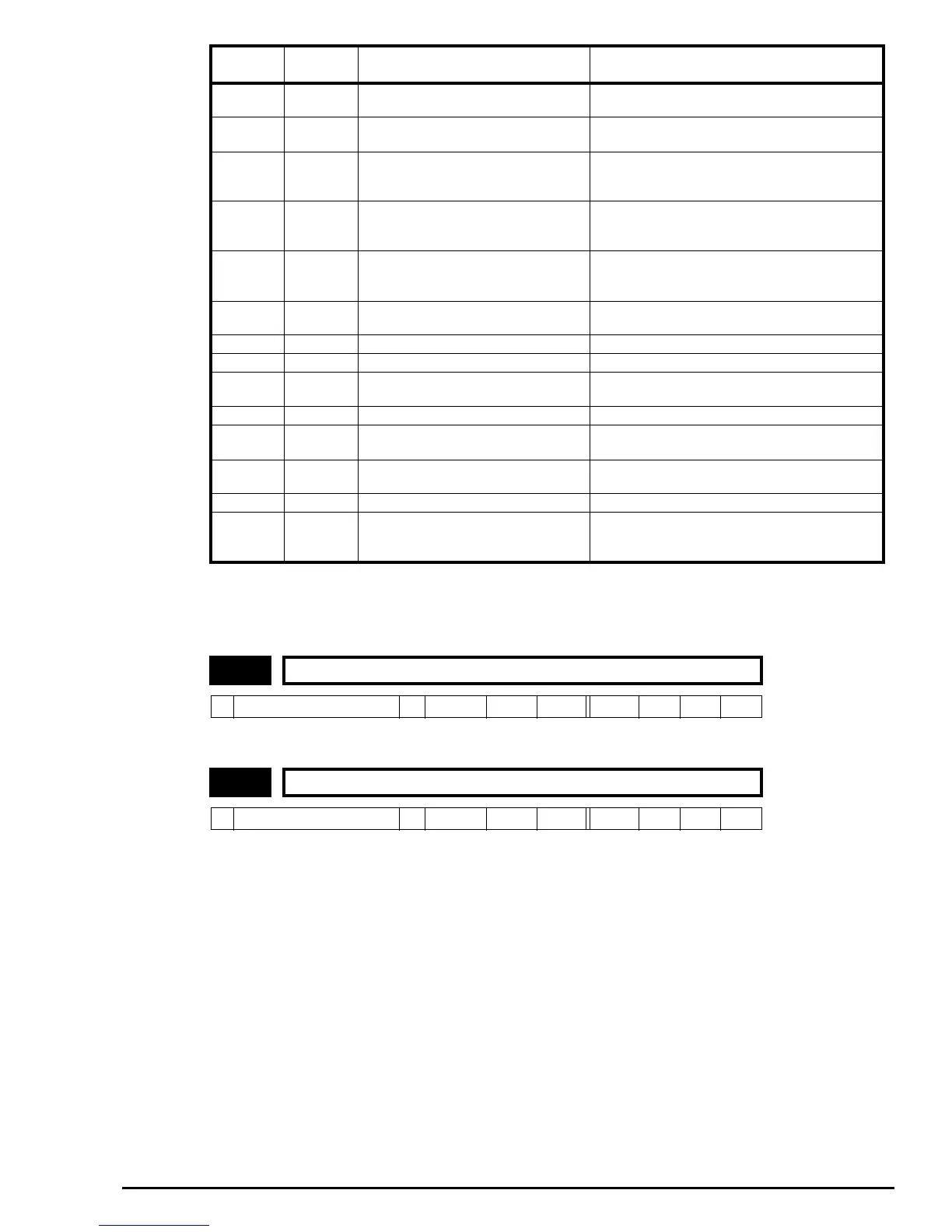
cL 28 Current loop loss on terminal 5
Input current less than 3mA when 4-20 or 20-4
modes used
SCL 30
User serial communications watchdog
failure
Failure of serial communications between drive and
master
EEF 31 Failure of internal EEPROM
Possible loss of parameter values
Corruption due to severe electrical noise
Set default parameters (see parameter 11.43)
PH 32 Phase loss
One of the input phases has become disconnected
from the drive. (This applies to 200V/400V three
phase units only, not dual rated units).
rS 33 Stator resistance measurement failure
Motor cable disconnected during measurement
Motor too small for drive
See parameter 5.12 for more details
trxx 40-99
User trips where xx is the user trip
number
F.bu s 180 Field bus disconnection whilst in use
C.Err 182 Quickey memory corrupt Bad connection or memory corrupt
C.dat 183 Quickey with no data
New / empty Quickey being read
Quickey / drive software compatibility issue
C.Acc 185 Quickey write fail Bad connection or faulty Quickey
C.rtg 186 Quickey voltage rating change
Already programmed Quickey read by drive of
different rating
O.Ld2 188
+28V serial communications power
supply overload
Overload of more than 110 mA or short circuit on
+28V serial communications power supply
O.cL†† 189 Current loop input overload Input current exceeded 25mA
Motor runs unstable
Motor or motor connections changed. Check motor
connections and re-autotune drive to motor (see
parameter 5.12)
10.30 Max full power braking time
Ú
0.0 ~ 400.0
Ö
0sRWUni
10.31 Max full power braking period
Ú
0.0 ~ 25.0
Ö
0minRWUni
Trip Code
Trip
Number
Condition Possible Cause