Manual Addendum
1010FMA-14
3
NOTE: The method used to create auxiliary current loops makes it impractical to gen-
erate the 2 mA fault current produced by the primary 4-20 mA outputs of the
meter.
NOTE: The 1010N-7 Expanded I/O Module auxiliary output signals (Aux Io1 - Aux Io4)
generated from Pgen1, Pgen2, Vo1 and Vo2 are “mirrored” output currents.
For example, if Vo1 is a 5 Vdc signal then Aux Io3 will be 12 mA.
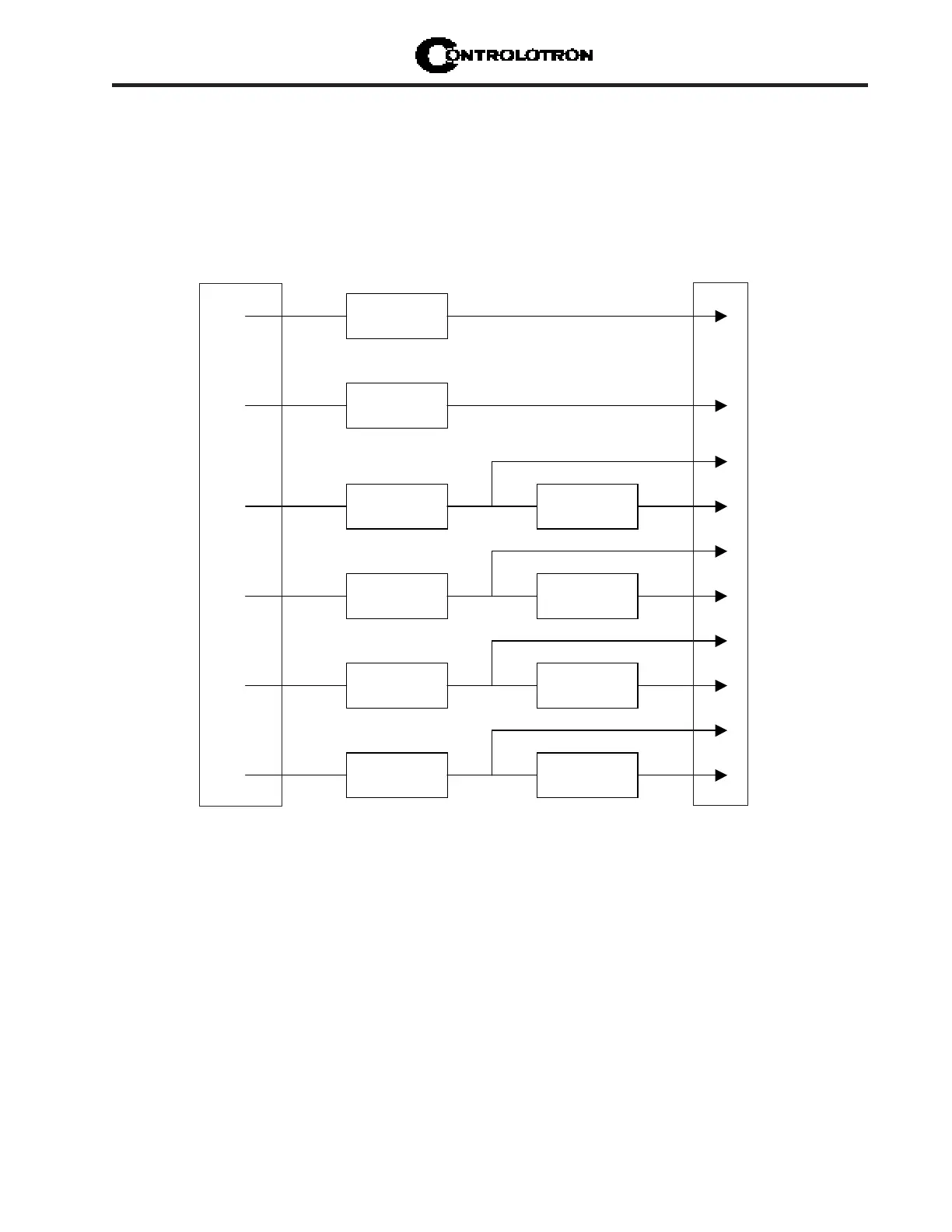
EXPANDED I/O MODULE OPTION PROGRAMMING
The diagram below illustrates the Expanded I/O Module Option programming for a Single
Channel meter with a 1010N-7 Expanded I/O Module.
F L O W C OM P UT E R
I N T E R N A L
C O N N E C T I O N S
I o 1
I o 1
Pgen1
Pgen2
V o 1
V o 2
Aux Io1
Aux Io2
Aux Io3
Aux Io4
O U T P U T
TER MINAL STRIP
l
l
l
l
yyy
yy
y