37
azimuth. Each MPPT employs a method known as perturb and
observe for seeking and tracking the maximum power point
along the I/V curve of the PV array. During operation each MPPT
will make small adjustments to the PV voltage and then
executes a power measurement; if the PV power increases,
further voltage adjustments in that same direction are performed
until the PV power no longer increases.
INSTRUCTION:
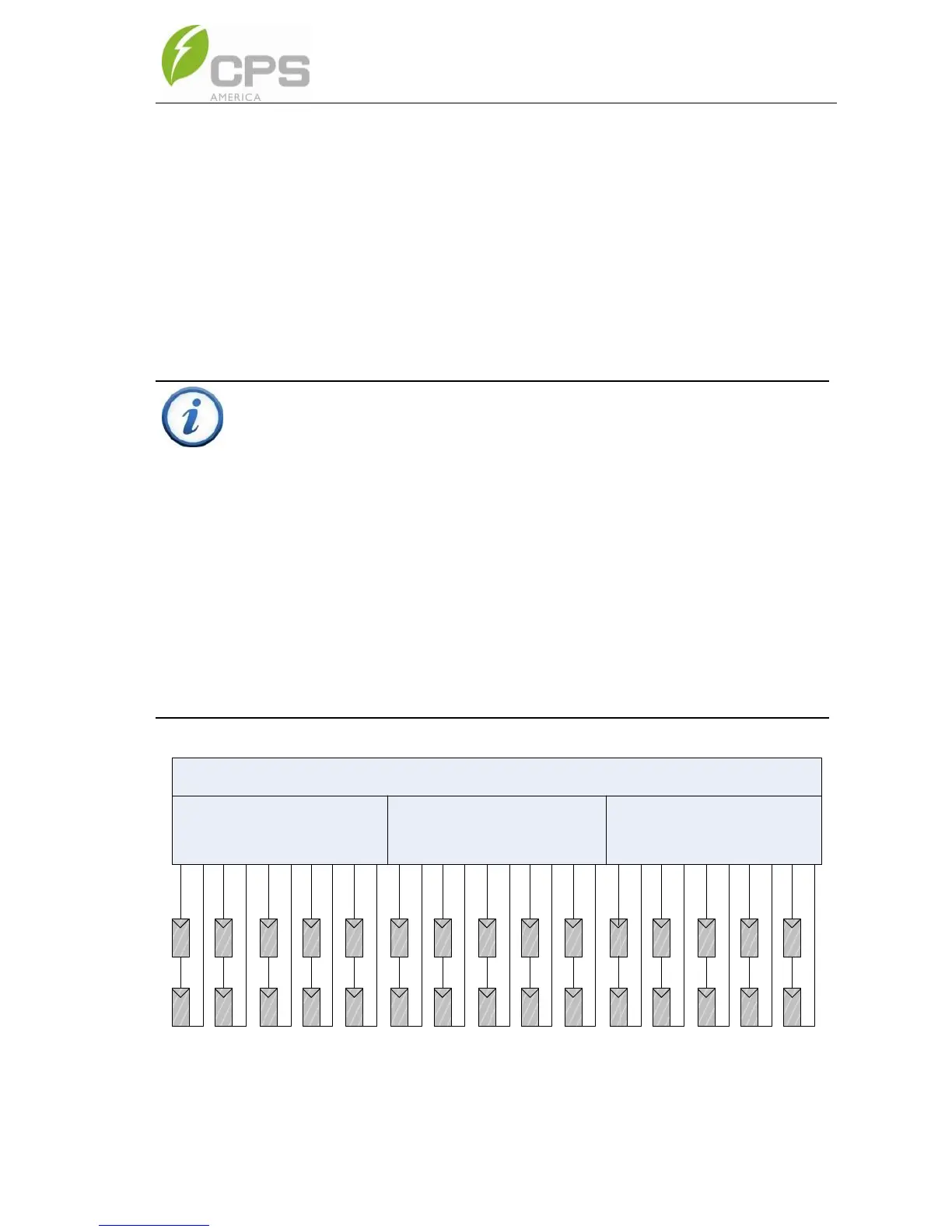
PV power should be balanced as much as possible between the three
MPPT zones. See Table 3-6 for string/zone combinations.
NOTE 1: Always attempt to connect an equal number of PV source
circuits to PVIn1, PVIn2 and PVIn3 to optimize the individual MPPT
zone, total inverter operation and energy harvest.
NOTE 2: Connecting all the inputs to only one will result in only
utilizing 33% of the inverter power.
NOTE 3: When designing the PV system ensure each PV string within
a single PV input zone includes the same module type (Mfg and
ratings), series module count, and module orientation (tilt and
azimuth) to maximize MPPT performance and energy harvest.