1+
SPD
2+ 3+ PE
AC Output:Use 90¡ãC wire, either 3~2/0AWG copper or
2~2/0AWG aluminum, torque 110 in-lbs.
AC Ground:Use 90¡ãC copper wire, 6~4AWG for internal
grounding bar or external grounding nut, torque 50 in-lbs.
L1 L2 L3 N
1 2 3
ON
OFF
S1
4
ON
OFF
S1
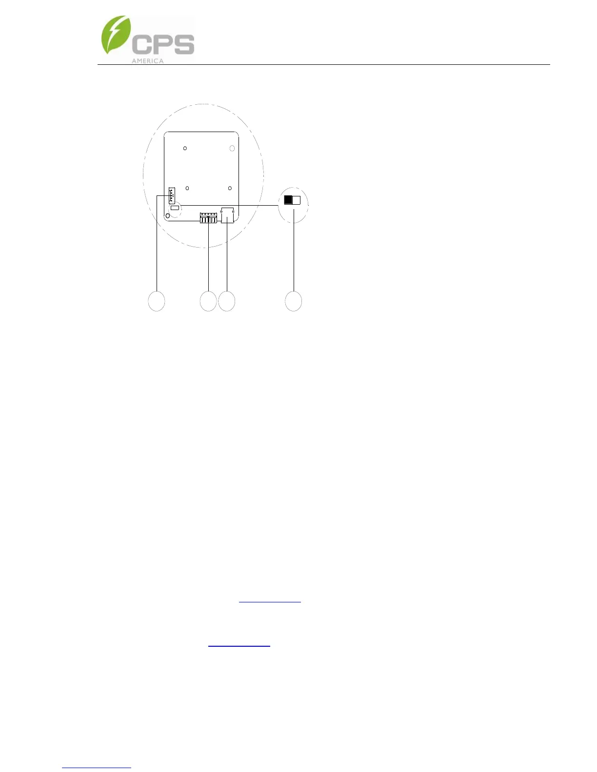
① RS485 P8 (Debug only)
1. 12V+
2. 12V
GND
3. RS485+
4. RS485-
5. COM
② RS485 P7 (Communcation)
1. 12V+
2. 12V
GND
3. RS485+
4. RS485-
5. COM
③ USB Port P6: Firmware
upgrade
④ Selector Switch (S1): 120Ω
terminal resistor switch for
communications.
1. ON: Enable the
termination resistance
2. OFF: Disable
termination resistance
3.4.2. RS485 Communication
CPS recommends the following cable for inverter RS485 communications:
UTP CAT-5e or (3) 18-22AWG communication cables.
It is recommended that industrial grade shielded RS485 cable be used in
lieu of unshielded twisted pair. Communication cable such as (CAT5) or
Belden 3106A cable for RS485 5 pin connector is preferred.
RS485 communication cables are connected via the 5-pin connector to the
port labeled (2) in Figure 3-40. When creating a network of multiple inverters,
the cables are terminated to the same 5-pin connector, double seating the
conductors. Figure 3-41 shows a single inverter communication connection
in (1) and a network configuration in (2).


 To Next Page