58
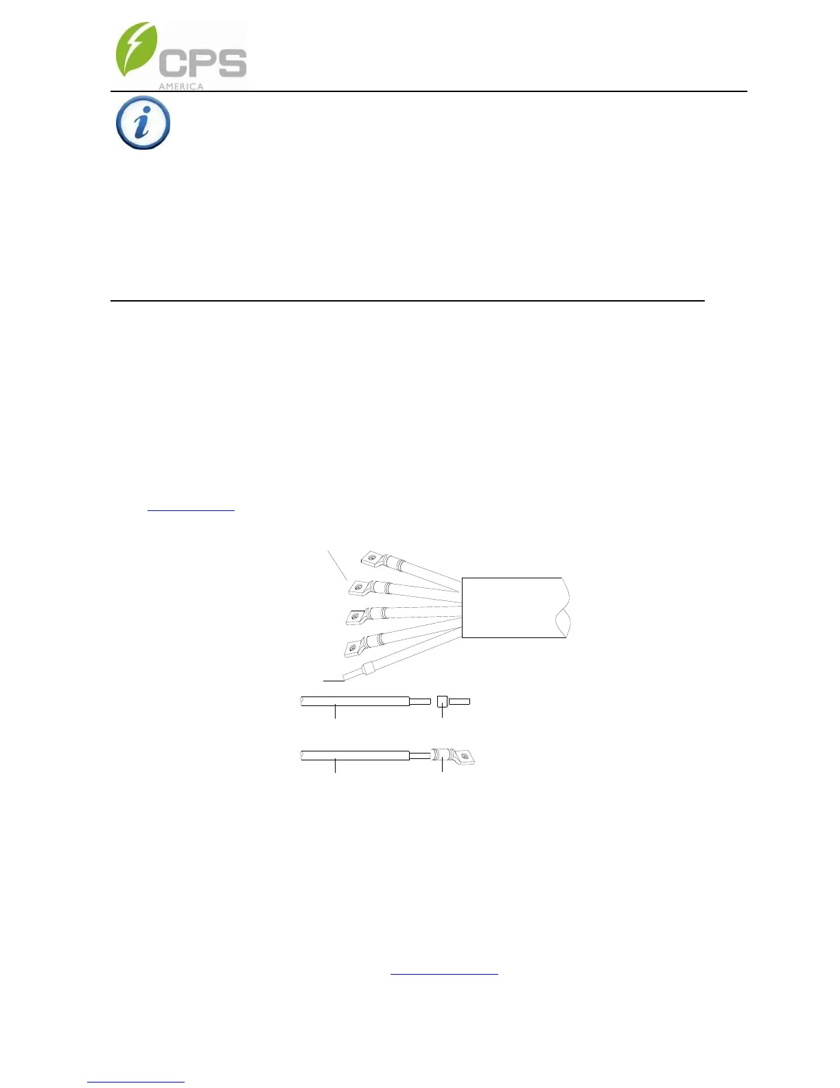
Use the OT type terminal to connect the AC conductors to the AC terminal block
and connect the PE (GND) cable to the grounding terminal block. The neutral
conductor is optional. The inverter may be wired as a 3-wire or 4-wire
connection, the PE ground is ALWAYS required. When terminating the ground
at the busbar a ferrule is recommended but not required. (See the 1
st
diagram in
Figure 3-33) Set up the conductors referring to Figure 3-35.
Pre-insulated end ferrule
1pcs
OT type terminal,4pcs
Pre-insulated end ferruleCore wire
OT type terminalCore wire
Figure 3-35 AC output and internal ground conductor set up
When bonding the inverter/mount to a metallic structure is required, use the OT
type terminal to connect the ground conductor to the external bonding point at
the bottom of the wiring box. The bonding point is located at the bottom of the
Standard wirebox as shown in Figure 3-36(a), the H4 wirebox as shown in
Figure 3-38(b).
INSTRUCTION:
The neutral conductor from the inverter to point of interconnection
(POI) is optional. The function of the neutral, when used, is to provide
a point of reference for measurement purposes that is essentially at
ground potential. The neutral conductor is for control or
measurement purposes only, and therefore may be sized according
to NEC section 705.95(B). The ground conductor (PE) is sized to
section 250.122.