TEST SETUP SWI-22-10-10
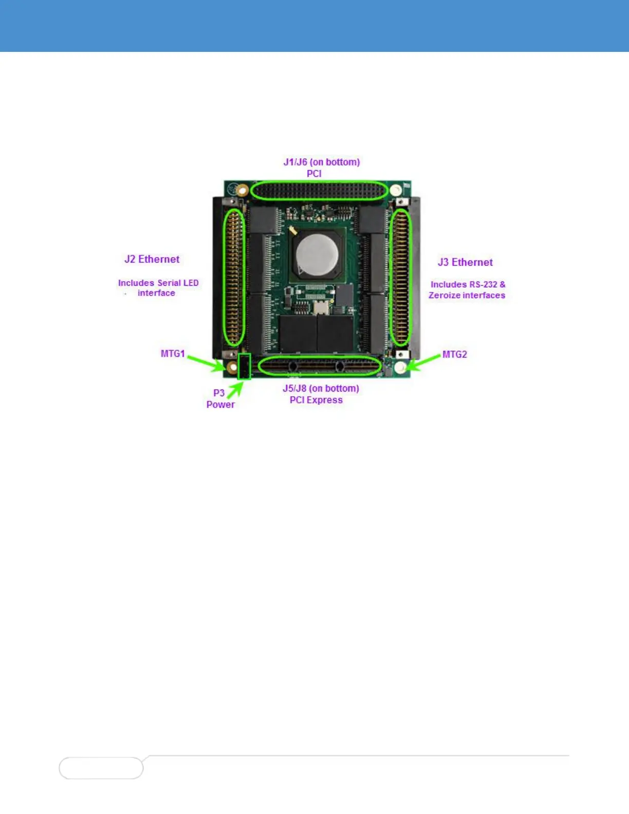
Figure 11 shows the location of the connectors on the SWI-22-10-10.
Figure 11. Connector Locations (SWI-22-10-10)
1. Place the card on an anti-static surface, such as the bag that the card was packaged in, or install it
into a PCI/104 or PCI/104-Express stack.
2. Connect the two Ethernet cables (CBL-2444-01 and -02) to the card, matching up the J2 and J3
labels on the cables with ports J2 and J3 on the card.
The Harwin connectors can’t be mated by just plugging them together. Match up the faces of the
mating connectors and use a small bladed screwdriver to screw in one of the captive screws part
way, then the other screw part way, then proceed to screw both screws in fully.
3. If the card is installed in a PCI/104 or PCI/104-Express stack, it will be powered by the stack. Skip to
step 4. Otherwise, connect power:
Connect the power cable CBL-2551-01 to the auxiliary power connector P3.
Attach the two ring lugs on the power cable to the two mounting holes on the board: one to MTG1
(chassis ground 1) and the other one to MTG2 (chassis ground 2), using the supplied screws,
star washers, and nuts.
Connect chassis ground 1 and chassis ground 2 either to the chassis ground of the bench-top
power supply or to the chassis ground of the PCI/104 stack. Failure to do so could affect data
transmission over long cables.
Connect the power cable banana plugs to a bench-top power supply that can supply 5V/3A.
4. Connect the DB-9 connector on CBL-2444-01 to an open serial port on your host computer for access
to the console (CLI). Use the supplied extension cable (CBL-1536-01) if a longer reach is needed.
5. Connect one Ethernet port to your host computer or to a network shared by your host computer for
access to the Web GUI management interface (GUI).
6. Connect other Ethernet ports to desired equipment for testing.
 Loading...