EasyManuals Logo

Curtiss-Wright Parvus SWI-22-10-10 User Manual

Curtiss-Wright Parvus SWI-22-10-10
107 pages
To Next Page IconTo Next Page
To Previous Page IconTo Previous Page
Page #56 background imageLoading...
Page #56 background image
Chapter 5 Connector Descriptions
Parvus SWI-22-10
Curtiss-Wright
Page 56 of 107
ECO-4823
Effective: 04 Oct 16
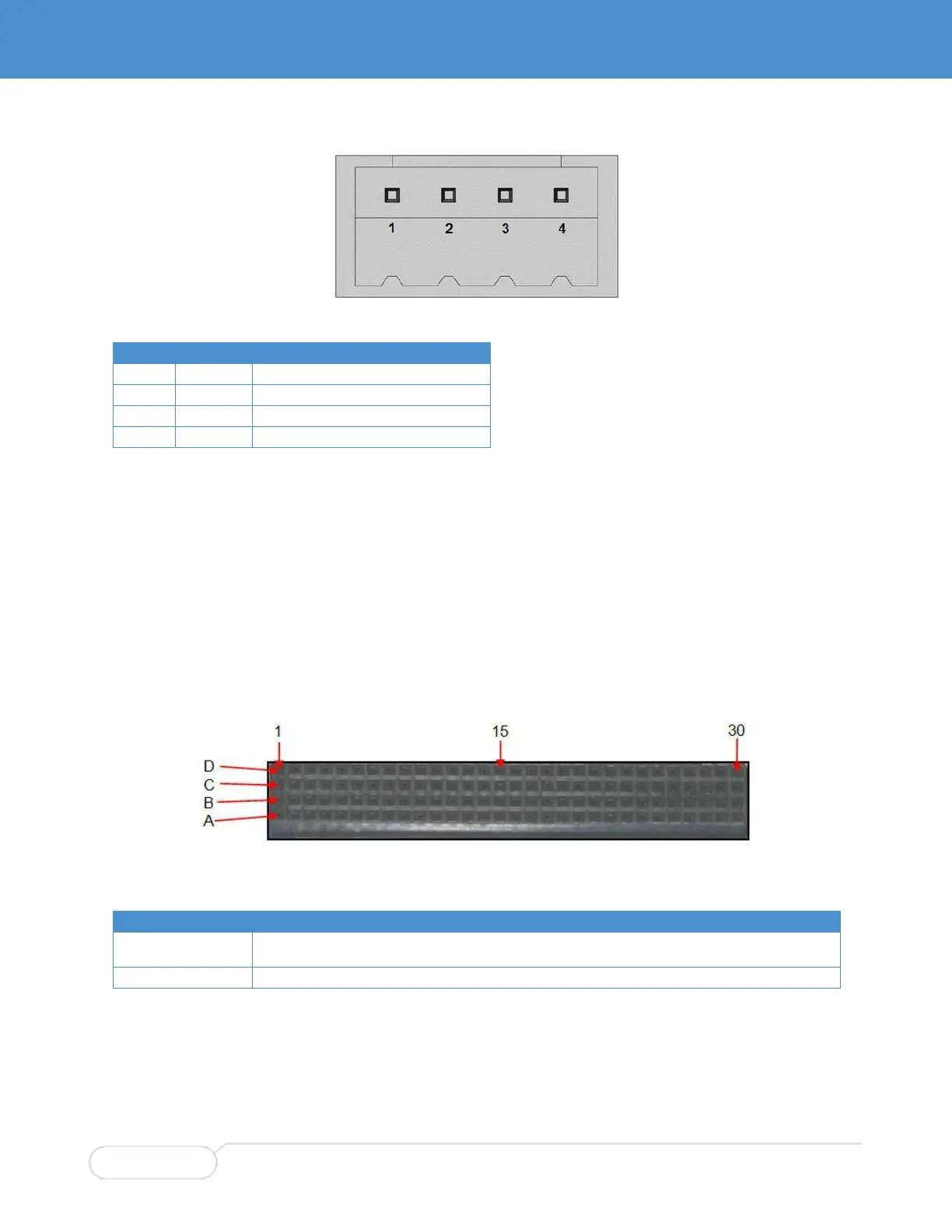
Figure 20. Auxiliary Power Connector Pin Orientation (P3)
P3 Pin
Signal
Description
1
+V
+3.0-5.5VDC Input (measured at P3)
2
+V
+3.0-5.5VDC Input (measured at P3)
3
GND
+V Return
4
GND
+V Return
MOUNTING HOLES (MTG1, MTG2)
Figure 19 shows the location of the card mounting holes. MTG1 and MTG2 must be connected to system
chassis ground via a 4-40 screw and star washer. Refer to "Test Setup SWI-22-10-10" or "Test Setup
SWI-22-10-01" for instructions.
PCI CONNECTORS (J1 & J6)
See www.pc104.org for standardization details.
Figure 21 shows the pin orientation for the PCI connectors.
Figure 21. PCI Connectors (J1 & J6)
J1 & J6 Signal
Pin List
GND
A1, A5, A10, A14, A20, A24, A28, B3, B9, B13, B18, B23, C4, C7, C12, C16, C22, C26, D5, D11, D15,
D20, D25, D27, D30
+5V
A22, A26, B21, B27, C1, C24, C28, D2

Table of Contents

Questions and Answers:

Question and Answer IconNeed help?

Do you have a question about the Curtiss-Wright Parvus SWI-22-10-10 and is the answer not in the manual?

Curtiss-Wright Parvus SWI-22-10-10 Specifications

General IconGeneral
BrandCurtiss-Wright
ModelParvus SWI-22-10-10
CategorySwitch
LanguageEnglish

Related product manuals