7. Turn on the power supply.
8. After about 18 seconds, a green LED should start flashing on the edge of the board next to the PCI-
Express connector. The flashing LED indicates that the card is ready for operation. During this boot
process the serial CLI port will output information about the progress of the booting process.
TEST SETUP SWI-22-10-01
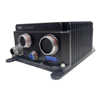
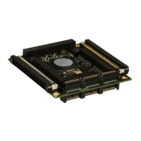
Figure 12 shows the location of the connectors on the SWI-22-10-01.
Figure 12. Connector Locations (SWI-22-10-01)
1. Place the card on an anti-static surface, such as the bag that the card was packaged in, or install it
into a PCI/104 or PCI/104-Express stack.
2. Connect the four Ethernet cables (CBL-2562-01, -02, -03, and -04) to the card, matching cables
labeled P10, P13, P14, and P15 to the corresponding ports on the card.
3. If the card is installed in a PCI/104 or PCI/104-Express stack, it will be powered by the stack. Skip to
step 4. Otherwise, connect power:
Connect the power cable CBL-2551-01 to the auxiliary power connector.
Attach the two ring lugs on the power cable to two mounting holes on the board: one to MTG1
(chassis ground 1) and the other one to MTG2 (chassis ground 2), using the supplied screws,
star washers, and nuts.
Connect chassis ground 1 and chassis ground 2 either to the chassis ground of the bench-top
power supply or to the chassis ground of the PCI/104 stack. Failure to do so could affect data
transmission over long cables.
Connect the power cable banana plugs to a bench-top power supply that can supply 5V/3A.
4. Connect the DB-9 connector on CBL-2562-01 to an open serial port on your host computer for access
to the console (CLI). Use the supplied extension cable (CBL-1536-01) if a longer reach is needed.
 Loading...