List of Figures
Figure 1. Management Interface Block Diagram SWI-22-10-10 ................................................................ 12
Figure 2. Management Interface Block Diagram SWI-22-10-01 ................................................................ 13
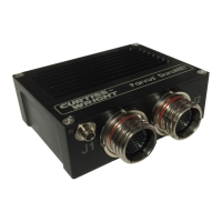
Figure 3. SWI-22-10-10 Card ..................................................................................................................... 14
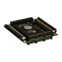
Figure 4. SWI-22-10-01 Card ..................................................................................................................... 15
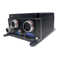
Figure 5. SWI-22-10 Card with Thermal Plate ........................................................................................... 15
Figure 6. Thermal Plate Mounting Hole Locations ..................................................................................... 16
Figure 7. Thermal Plate Vertical Dimensions ............................................................................................. 16
Figure 8. Thermal Plate Horizontal Dimensions ........................................................................................ 17
Figure 9. Breakout Cableset (CBL-SWI-22-10-10) .................................................................................... 20
Figure 10. Breakout Cableset (CBL-SWI-22-10-01) .................................................................................. 21
Figure 11. Connector Locations (SWI-22-10-10) ....................................................................................... 22
Figure 12. Connector Locations (SWI-22-10-01) ....................................................................................... 23
Figure 13. CLI Functional Groups .............................................................................................................. 31
Figure 14. Web GUI Top Level Features (Alphabetized) ........................................................................... 36
Figure 15. SWI-22-10-10 Ethernet Connectors ......................................................................................... 50
Figure 16. SWI-22-10-10 Ethernet Connector Detail ................................................................................. 51
Figure 17. SWI-22-10-01 Ethernet Connectors ......................................................................................... 53
Figure 18. SWI-22-10-01 Ethernet Connector Detail ................................................................................. 54
Figure 19. SWI-22-10 Common Connectors .............................................................................................. 55
Figure 20. Auxiliary Power Connector Pin Orientation (P3) ....................................................................... 56
Figure 21. PCI Connectors (J1 & J6) ......................................................................................................... 56
Figure 22. Recommended SWI-22-10-10 LED Port Interface Circuit ......................................................... 59
Figure 23. Recommended SWI-22-10-01 LED Port Interface Circuit ......................................................... 59
Figure 24. CLI Mode Transition Commands .............................................................................................. 93
 Loading...