Appendix J – General Purpose Input Output Port Applications
Class Series 2 Programmer’s Manual 257
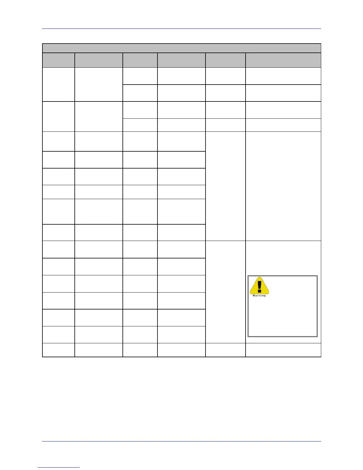
Applicator Interface Card (Type 1) GPIO Port (J2) Overview
Pin
Number
Signal
Name
Signal
Direction
Active
Setting
Jumper
Placement
Function /
Description
Ground Ground JMP 7 “On”
Printer chassis ground is
used
1
Ground
(Configurable)
Open Open JMP 7 “Off”
Ground return must be
supplied
Output +5 VDC JMP 8 “On”
Printer +5 VDC is used
(.5 amp max.)
2
+5 VDC
(Configurable)
Open Open JMP 8 “Off” +5 VDC must be supplied
3
Start Of
Print
[3]
Input Programmable
4
Slew
Label
Input Programmable
5
Pause
Toggle
Input Low
6 Reprint
[2]
Input Low
7
+24 VDC
(1.0 amp
max.)
Output +24 VDC
8 Ground Ground Ground
N/A N/A
9
Ribbon
Low
Output Programmable
10
Service
Required
[1]
Output Low
11
End Of
Print
Output Programmable
12
Media
Out
Output Low
13
Ribbon
Out
Output Low
14
Data Ready
(DRDY)
Output Low
JMP 9:
Pins 1 & 2
= +5 VDC
– OR –
Pins 2 & 3 =
+24 VDC
When inactive, all output
pins will be pulled up to
the voltage determined
by this jumper setting.
Failure to
configure the card
for the device(s) you
are connecting may
result in damage to
the printer and/or
the applicator.
15 Spare
Output N/A N/A N/A
[1]
Evoked by occurrences listed under “Fault Messages” in the A-Class Operator’s Manual.
[2]
Reprints the last label exactly, with no increment or time stamp changes; use it for error
conditions. Always keeping this signal LOW will result in non-stop printing.
[3]
If active with no current print job, “WAITING FOR DATA” is displayed. Specifying a quantity of 9999
while always keeping this signal “On” will cause non-stop label printing, except in single label mode
(see Imaging Mode, Section 4.2.5 of the A-Class Operator’s Manual), which will cause the printer to
stop between labels.

 Loading...