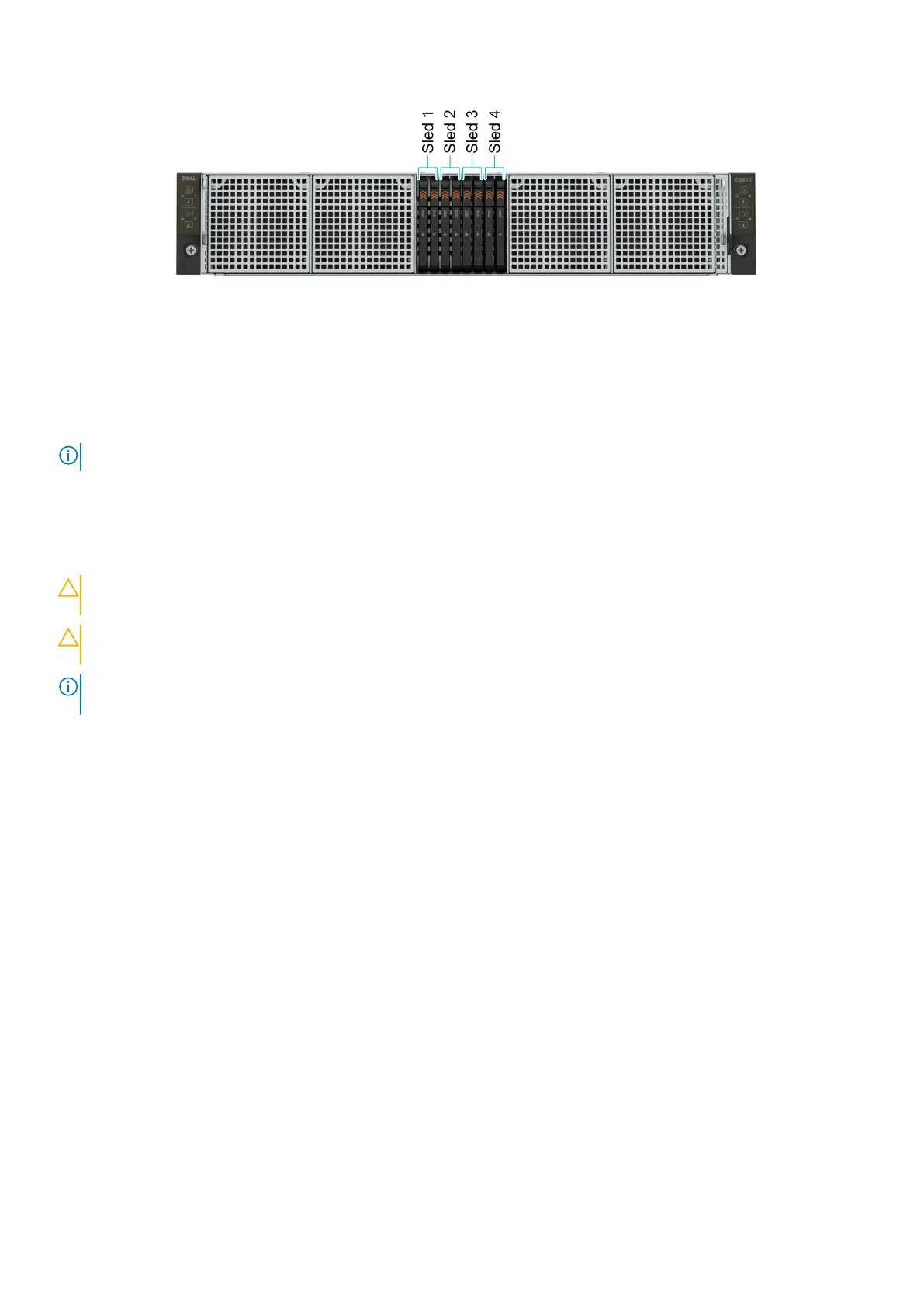
Figure 94. Sled to drive mapping for 8 x E3.s drive configuration
1. Drives 0–1 mapped to sled 1
2. Drives 2-3 mapped to sled 2
3. Drives 4-5 mapped to sled 3
4. Drives 6-7 mapped to sled 4
NOTE: The warranty of the drives are linked to the Service Tag of the corresponding sled.
Removing the backplane
Prerequisites
CAUTION:
To prevent damage to the drives and backplane, you must remove the drives from the system before
removing the backplane.
CAUTION: You must note the slot number of each drive and temporarily label them before removal so that you
can replace them in the same slots.
NOTE: Observe the routing of the cables on the chassis as you remove them from the system. You must route these cables
properly when you replace them to prevent the cables from being pinched or crimped.
1. Follow the safety guidelines listed in Safety instructions.
2. Follow the procedure listed in Before working inside your system.
3. Remove the drive cage.
4. Disconnect all the cables from the backplane.
Steps
1. Using the Phillips 2 screwdriver, remove the screws that secure the backplane to the drive cage.
2. Lift the backplane away from the drive cage.
88
Installing and removing system components