About this task
The following images indicate the location of the left/video fan and provide a visual representation of the removal procedure.
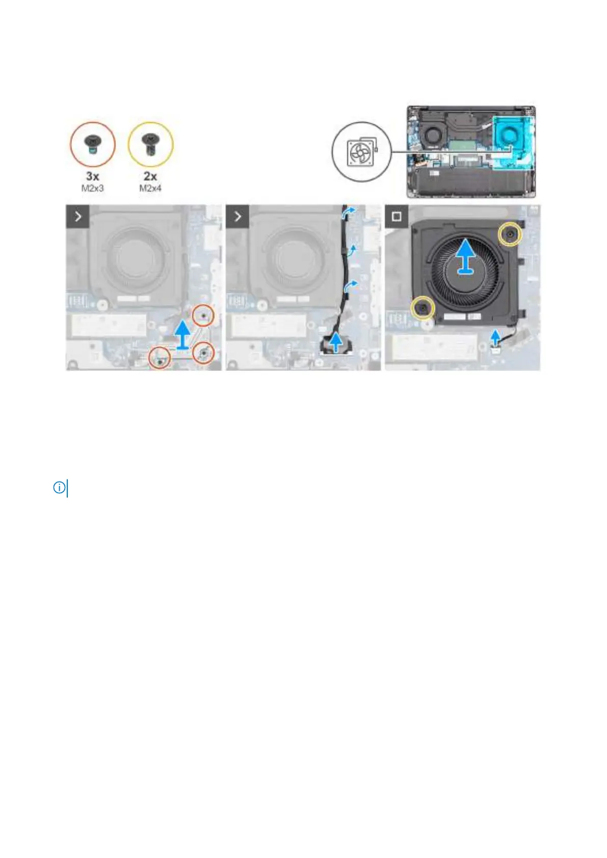
Figure 36. Removing the left/video fan
Steps
1. Remove the three screws (M2x3) that secure the display-cable bracket to the system board.
2. Lift the display-cable bracket off the system board.
3. Disconnect the display cable from the connector (LCD1) on the system board.
4. Disconnect the IR-camera cable from the connector (CAM1) on the system board.
NOTE: This step applies only to computers shipped with an IR camera installed.
5. Remove the display cable and the IR-camera cable, if available, from the routing guides on the fan.
6. Disconnect the fan cable from the connector (FANR2) on the system board.
7. Remove the two screws (M2x4) that secure the fan to the palm-rest assembly.
8. Lift the left/video fan off the palm-rest assembly.
Installing the left/video fan
Prerequisites
If you are replacing a component, remove the existing component before performing the installation procedure.
About this task
The following images indicate the location of the left/video fan and provide a visual representation of the installation procedure.
Removing and installing Customer Replaceable Units (CRUs)
69