Figure 55. Installing the display assembly
Steps
1. Place the display assembly on a clean and flat surface.
2. Hold the palm-rest assembly at an angle and slide the palm-rest assembly under the display hinges.
CAUTION: To avoid damaging the display, do not slide the palm-rest assembly over the display assembly.
3. Close the display hinges to align the screw holes on the display hinges with the screw holes on the palm-rest assembly.
4. Replace the six screws (M2.5x5) to secure the display hinges to the palm-rest assembly.
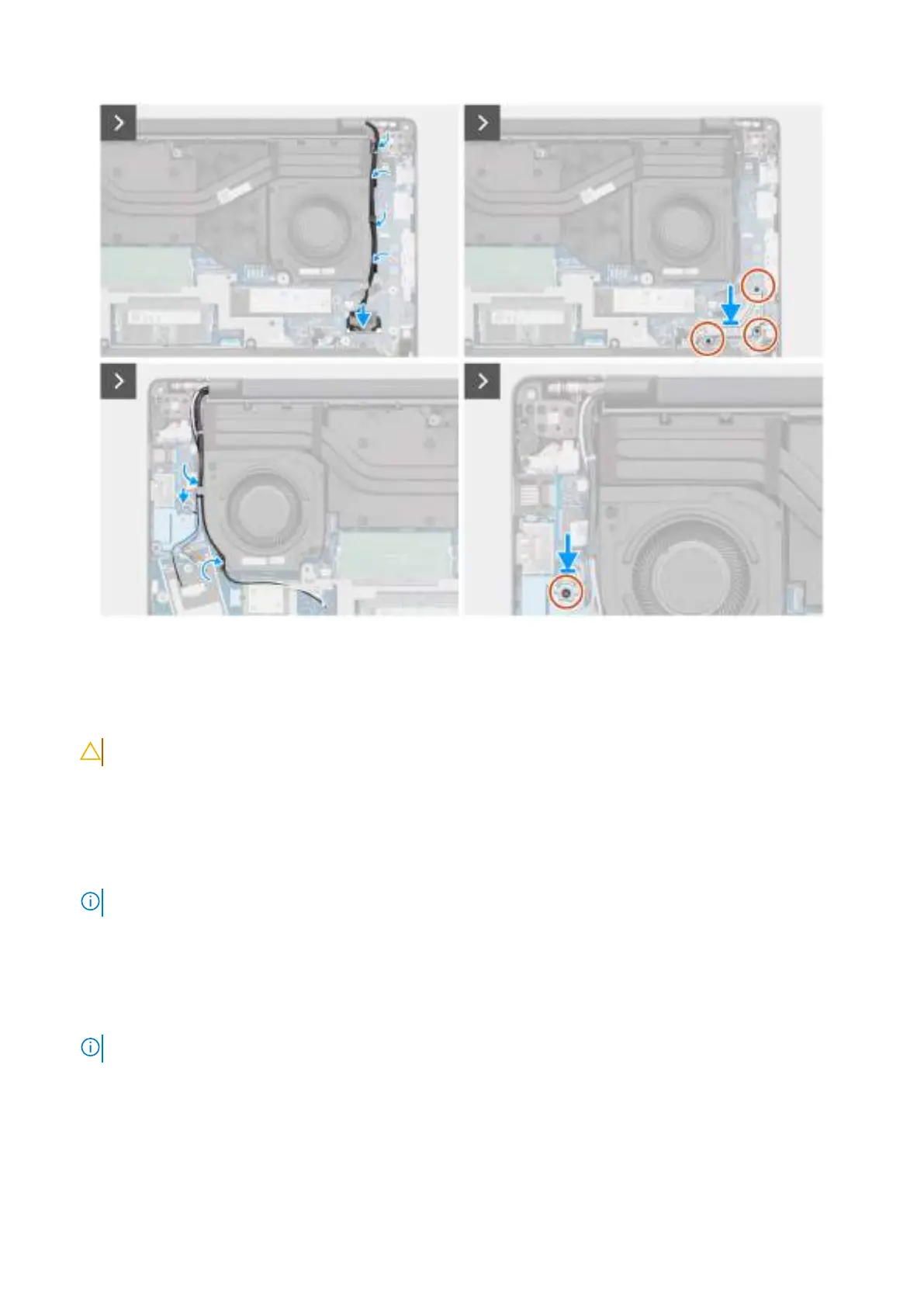
5. Route the display cable and the IR-camera cable, if available, through the routing guides on the left/video fan.
6. Connect the display cable to the connector (LCD1) on the system board.
7. Connect the IR-camera cable to the connector (CAM1) on the system board.
NOTE: This step applies only to computers shipped with an IR camera installed.
8. Align and place the display-cable bracket over the display cable and the IR-camera cable, if available, on the system board.
9. Replace the three screws (M2x3) to secure the display-cable bracket to the system board.
10. Route the wireless-antenna cables and WWAN-antenna cables, if available, through the routing guides on the right/
processor fan.
11. Connect the Darwin-antenna cable to the connector (DARWIN) on the system board.
NOTE: Steps 10 to 12 apply only to computers shipped with a WWAN module installed.
12. Align and place the Darwin-cable bracket over the Darwin-antenna cable on the system board.
13. Replace the screw (M2x3) to secure the Darwin-cable bracket to the system board.
Next steps
1. Install the WWAN module, if available.
Removing and installing Field Replaceable Units (FRUs)
89