Analog Output Settings (R1-EC9144) EtherCAT Programming Guide
24-6 March, 2017
24
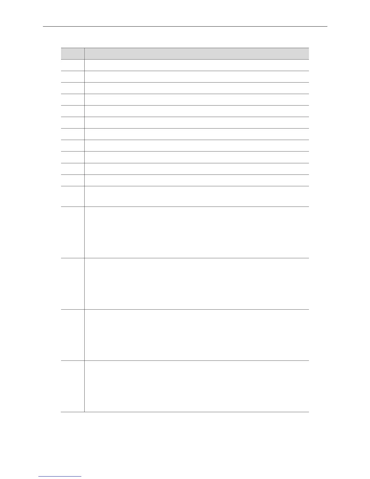
List of _ECAT_Slave_AIO_Get_Output_ReturnCode
Bit Description
0 Iout_3 error: This bit is set if an error is detected on current output channel 3.
1 Iout_2 error: This bit is set if an error is detected on current output channel 2.
2 Iout_1 error: This bit is set if an error is detected on current output channel 1.
3 Iout_0 error: This bit is set if an error is detected on current output channel 0.
4 Vout_3 error: This bit is set if an error is detected on voltage output channel 3.
5 Vout_2 error: This bit is set if an error is detected on voltage output channel 2.
6 Vout_1 error: This bit is set if an error is detected on voltage output channel 1.
7 Vout_0 error: This bit is set if an error is detected on voltage output channel 0.
8 Overheat: This bit is set If temperature of the AD converter chip is over 150°C.
9 Ramp active: This bit is set while any one of the output channel is slewing.
10 PEC error: Denotes a PEC error on the last data-word received over the SPI interface.
11
PEC enabled: This is a read only bit. It allows the user to verify the status of the packet error
checking feature.
12
DC-DC3: In current output mode, this bit is set on channel 3 if the dc-to-dc converter cannot
maintain compliance (it may be reaching its maximum voltage.
In voltage output mode, this bit is set if, on channel 3, the dc-to-dc converter is unable to regulate
to 15 V as expected.
When this bit is set, it does not result in the error pin going high.
13
DC-DC2: In current output mode, this bit is set on channel 2 if the dc-to-dc converter cannot
maintain compliance (it may be reaching its maximum voltage.)
In voltage output mode, this bit is set if, on channel 2, the dc-to-dc converter is unable to regulate
to 15 V as expected.
When this bit is set, it does not result in the error pin going high.
14
DC-DC1: In current output mode, this bit is set on channel 1 if the dc-to-dc converter cannot
maintain compliance (it may be reaching its maximum voltage.).
In voltage output mode, this bit is set if, on channel 1, the dc-to-dc converter is unable to regulate
to 15 V as expected.
When this bit is set, it does not result in the error pin going high.
15
DC-DC0: In current output mode, this bit is set on channel 0 if the dc-to-dc converter cannot
maintain compliance (it may be reaching its maximum voltage.).
In voltage output mode, this bit is set if, on channel 1, the dc-to-dc converter is unable to regulate
to 15 V as expected.
When this bit is set, it does not result in the error pin going high.