EtherCAT Programming Guide EtherCAT Operation Example
March, 2017 3-49
3
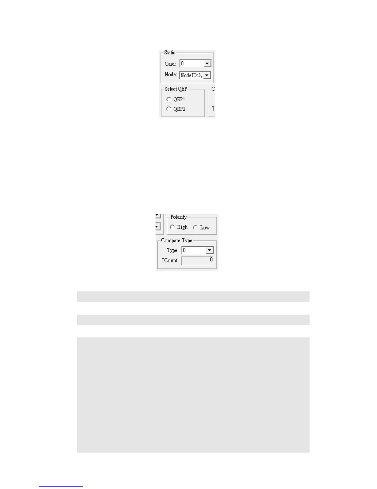
(2) Select the Card No., Node ID, and QEP
Figure 3.11.2.2
Card: Select the EtherCAT PCI motion card No. to be used.
Node: Select the Node ID; in the example, this axis will generate pulse for comparison.
QEP1: Select channel 1 for pulse input. (It should correspond to the physical wiring of QA1
and QB1.)
QEP2: Select channel 2 for pulse input.
(It should correspond to the physical wiring of QA2
and QB2.)
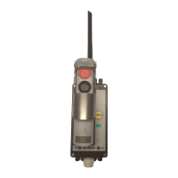
(3) Select Polarity and Compare Type
Figure 3.11.2.3
High: Select this option to carry out the following program: 1: High (high-level trigger)
rt = _ECAT_Compare_Set_Channel_Polarity (gu16_CardNo, 1);
Low: Select this option to carry out the following program: 0: Low (low-level trigger)
rt = _ECAT_Compare_Set_Channel_Polarity (gu16_CardNo, 0);
Type: Select the differential signal channel for the triggered signal.
rt = _ECAT_Compare_Set_Channel_Source (gu16_CardNo, u16_Channel, gu16_Qep);
// u16_Channel:
// 0 = Channel 0 (CMP_1) for outputting the differential signal. (Compare the pulse at a
fixed pulse interval.)
// 1 = Channel 1 (CMP_2) for outputting the differential signal. (Compare the pulse at
user-defined pulse intervals.)
// gu16_Qep
// 0 = When setting QEP1, this parameter is 0, which means the compared pulse is from
the first QA and QB.
// 1 = When setting QEP2, this parameter is 1, which means the compared pulse is from
the second QA and QB.