User Manual DEV 1951
12 Copyright DEV Systemtechnik GmbH 2004-2017
The second functionality of the mode (or "Local") push button is the event
acknowledgment: If there are pending and not acknowledged event(s), this is
indicated –in addition to the alarm connector, please refer to chapter 6.1.2- at the
device panel via continuous alternate blinking of all channel LEDs, the "Individual"
LED, and the "Simultaneous" LED (see below). To acknowledge the event(s) (i.e. to stop
the event indication and thus the blinking of the LEDs at the device panel), the
mode push button is to be operated. Thus, three scenarios for the behavior of the
mode push button are to be considered:
1. There are no pending and not acknowledged event(s):
In this case, the operation mode can be altered as described above.
2. There are pending and not acknowledged event(s) in Local Mode:
In this case, a short operation of the push button acknowledges the event(s).
After that, the operation mode can be altered as described above.
3. Pending and not acknowledged event(s) in Remote Mode (or Auto Mode):
In this case, a short operation of the push button acknowledges the event(s)
and switches the device to Local Mode. After that, the operation mode can be
altered as described above.
Note:
The type of event causing the event indication can be identified via Web
Interface or via remote interface, only.
If an event is not acknowledged and if the event disappears (e.g. a detected
missing AC line is working again), the event indication will stop automatically (if
it is the sole event).
The event indication cannot be stopped if no switch (or distribution amplifier)
module is installed or detected within the device.
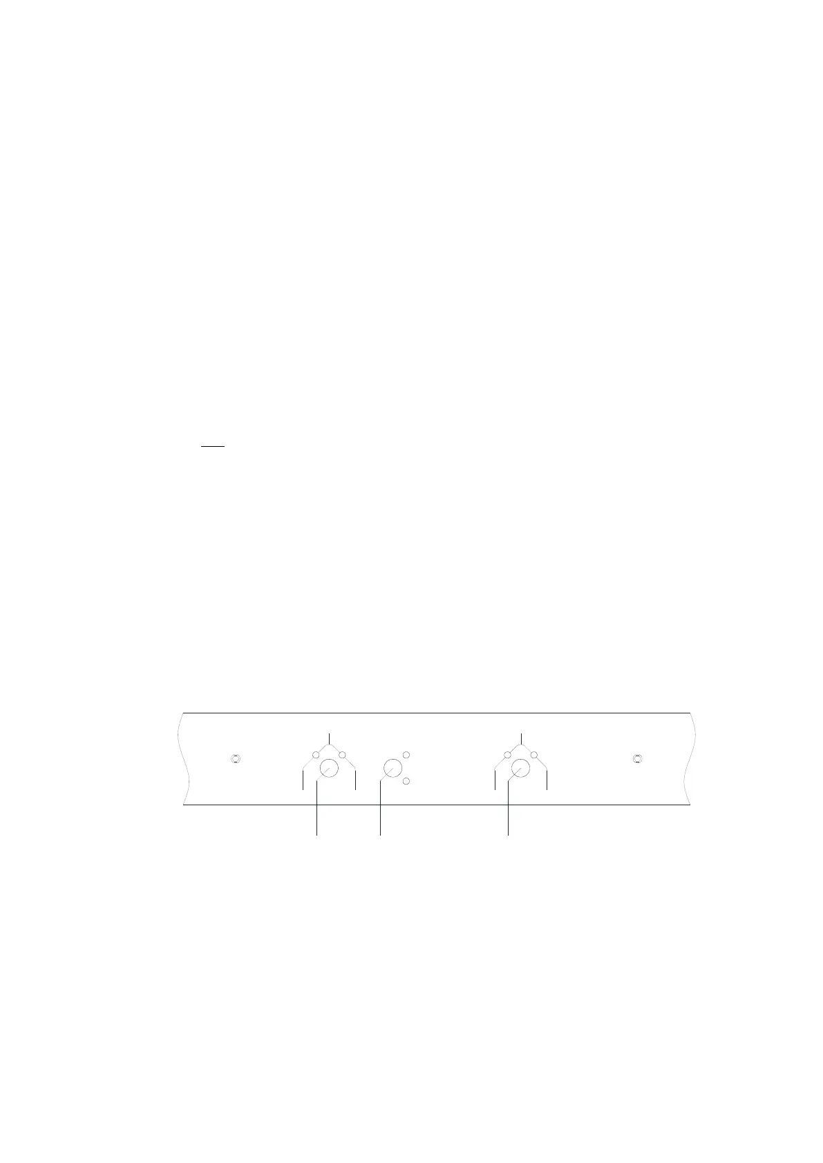
In the middle of the device panel, the following elements are located:
the channel push buttons and the green channel LEDs (5 & 7) and
the switching mode push button and the yellow LEDs (6) for the Simulta-
neous/Individual switching mode functionality (please refer to chapter 5.1.4):
In A In B
Ch 1
Individual
Sim ultaneous
5
6
7
In A In B
Ch 2
With the channel push buttons labeled "Ch 1" and "Ch 2", one of the two (input) ports
(primary (input) port "In A" or secondary (input) port "In B") of a switch module can
be switched to the common (output) port in Local Mode (!). The (input) port that is
currently active is indicated via the related green channel LED.
To alter the routing of a single switch module via the related channel push button
make sure that the device is in Local Mode and that the "Individual" LED is lit. After
the operation of the desired channel push button, the LED display will indicate the
altered switching position as a receipt.