User Manual DEV 1951
Copyright DEV Systemtechnik GmbH 2004-2017 11
3 Product Description
With the DEV 1951, DEV Systemtechnik has developed a modular design principle
for a universal dual channel switch chassis. A variety of different switch modules is
available that can be installed in the two slots of the device. A selection of passive
splitter modules and of distribution amplifier modules for ASI/SDI signals is avail-
able as well. Please refer to chapter 3.2 for the description of the single modules.
A device panel (chapter 3.1.1) permits the monitoring and the local control of the
DEV 1951. Some other methods for the control and for the surveillance of the
device are provided (chapter 3.1.2). The application of sensing switch modules and
of digital signal switch modules enables additional autonomous switching
capabilities of the DEV 1951 (chapter 3.1.3) as well as the application of the TRAC
(stands for "Trap Receiver Action Controller") option (chapter 3.1.4).
3.1 Features and Options
3.1.1 Device Panel
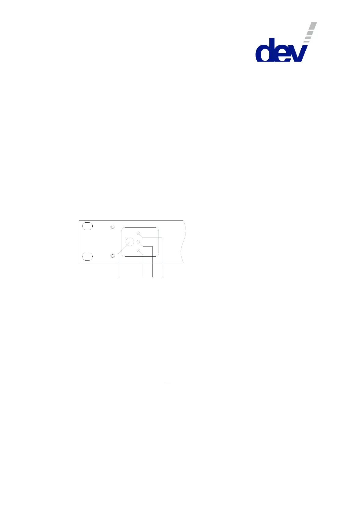
The DEV 1951 provides a device panel at the front side of the chassis. A mode push
button and three yellow LEDs are located at the left side:
Universal Sw itch C hassis
Local
Rem ote
DEV 1951
Auto
1 2 3
4
The mode push button (1) permits the change of the operation mode (please refer
to chapter 5.1) at the device. By pressing and holding the button for ~3 seconds the
status of the LEDs advances, i.e. always only one of the operation mode LEDs
"Auto" (2), "Local" (3), or "Remote" (4) is on.
Note:
Products with the preceding version of the device panel are providing a "Local"
push button (instead of the mode push button) and a single "Remote" LED (i.e.
there is no explicit "Local" or "Auto" LED). The behavior of the push button and
the LED differs: The "Local" push button realizes the same functionality as the
mode push button but the device can be toggled between Local Mode ("Remote"
LED off) and Remote Mode or Auto Mode ("Remote" LED on) and vice versa,
only. Switching from Local Mode via the "Local" push button toggles to the
preceding mode (Remote Mode or Auto Mode) which was activated before the
device had been switched to Local Mode. The explicit activation of Remote
Mode or of Auto Mode is performed via Web Interface (chapter 5.5.2), or via
SNMP (chapter 5.9.4.3.1), or via Sandar Prosan protocol (chapter 5.6.3.6).
Moreover, even older revisions of the DEV 1951 additionally provide a "Reset"
push button located left to the "Remote" LED and to the "Local" push button. This
"Reset" button is not supported by the firmware of the device. Please do not
operate the button it might have an impact on the behavior of the installed
switch modules!