User Manual DEV 1951
24 Copyright DEV Systemtechnik GmbH 2004-2017
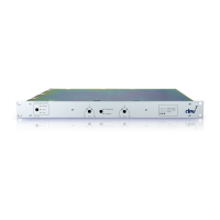
3.2.27 DEV 7463
1:2 Optribution® Switch; 1260…1610 nm; SC/APC
A
B
Com
Optical S witch
Op tical F ib er
External
Controller
Logic
Op tical F ib er
Op tical F ib er
Com
A B
The functionality of the DEV 7463 (here shown with the FC/APC connector option)
is identical with the DEV 7462 (please refer to chapter 3.2.26), but the module is
designed for a different optical wavelength range.
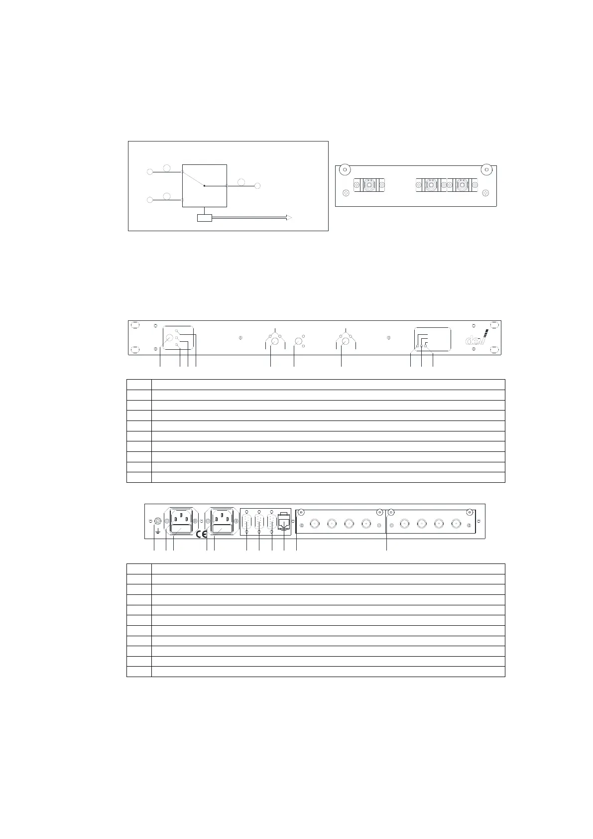
3.3 Product Drawings
Front View:
Univers al Switch Chass is
Lo cal
Rem ote
DEV 1 951
In A In B
Ch 1
Indiv idual
Sim ultaneou s
Auto
Power Supply 1
Power Supply 2
Failu re
1
5
6
7
8 9 102 3
4
In A In B
Ch 2
Yellow LED indicating "Auto" Mode
Yellow LED indicating "Local" Mode
Yellow LED indicating "Remote" Mode
Channel push button and green LEDs "In A" & "In B" for the primary channel "Ch 1"
Switching mode push button and yellow LEDs "Simultaneous" & "Individual"
Channel push button and green LEDs "In A" & "In B" for the secondary channel "Ch 2"
Green LED indicating the operation of "Power Supply 1"
Green LED indicating the operation of "Power Supply 2"
Red LED indicating a "Failure" of one of the power supplies
Rear View:
W AR N ING :
D isco nn ect po wer
be for e o pen ing !
1 2 3
4 5
6
7
8 9 10
Fuse 2 A T Fuse 2 A T
100 ...2 40 V
50 ...6 0 H z
40 VA
11
In B
Monitor
Out In A
DEV 11 -0005
In B
Monitor
Out In A
DEV 11 -0005
Alarm DIG /In RS 23 2 Ethe rne t
Channe l 2Channe l 1
AC plug for power supply unit 1
Fuse for power supply unit 1
AC plug for power supply unit 2
Fuse for power supply unit 2
"Alarm" connector, Sub-D 9 (m)
"Dig/In" connector, Sub-D 9 (f) for the digital interface
"RS 232" connector, Sub-D 9 (f) for the serial interface
"Ethernet" connector, RJ-45
Module slot "Channel 1" (here equipped with a DEV 11-0005 switch module )
Module slot "Channel 2" (here equipped with a DEV 11-0005 switch module )