User Manual DEV 1951
Copyright DEV Systemtechnik GmbH 2004-2017 41
5.4 Control via the Digital Interface
The digital interface of the DEV 1951 provides basic remote switching functionality,
e.g. for the control via a PLC (Programmable Logic Control).
The connector for the digital interface (SubD-9 (f), labeled "DIG/In") is located at the
rear side of the chassis, please refer to chapter 7 for the pin assignment.
Note:
Since the digital interface is defined as a remote interface, it only works if the
device is in Remote Mode.
If the device is equipped with a single switch module, only the contacts for
Channel 1 are monitored for operation.
If the device is equipped with two switch modules and if the switching mode is
set to Simultaneous switching mode (chapter 5.1.4), only the contacts for
Channel 1 are monitored for operation.
The switching commands via the digital interface will override switching
commands issued via SNMP or via any CPH protocol (Sandar Prosan, Leitch, or
QEC), i.e. the digital interface has a higher priority.
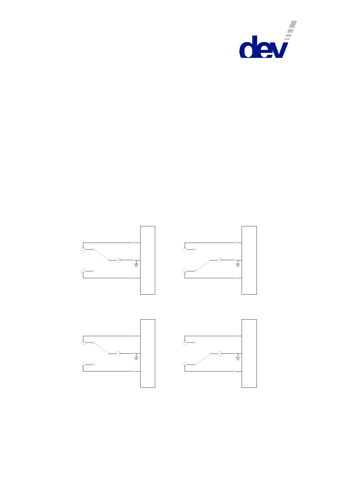
The following figure shows how the switch module setting works when using the
digital interface:
1951
PIN 9
PIN 8
PIN 7
1951
1951
1951
Individual: Channel 1, Port "In A"
Simultaneous: both channels, Port "In A"
PIN 9
PIN 8
PIN 7
PIN 3
PIN 2
PIN 1
PIN 3
PIN 2
PIN 1
Individual: Channel 1, Port "In B"
Simultaneous: both channels, Port "In B"
Individual: Channel 2, Port "In A"
Simultaneous: (not functional)
Individual: Channel 2, Port "In B"
Simultaneous: (not functional)