User Manual DEV 1951
Copyright DEV Systemtechnik GmbH 2004-2017 13
If the "Simultaneous" LED is lit (for the preconditions to activate Simultaneous
switching mode please refer to chapter 5.1.4), any of the two channel push buttons
can be operated to initiate the switching of the two installed switch modules.
Note:
If the device is equipped with a single switch module only, the channel push
button of the empty slot will not work. In addition, the Simultaneous switching
mode is not available.
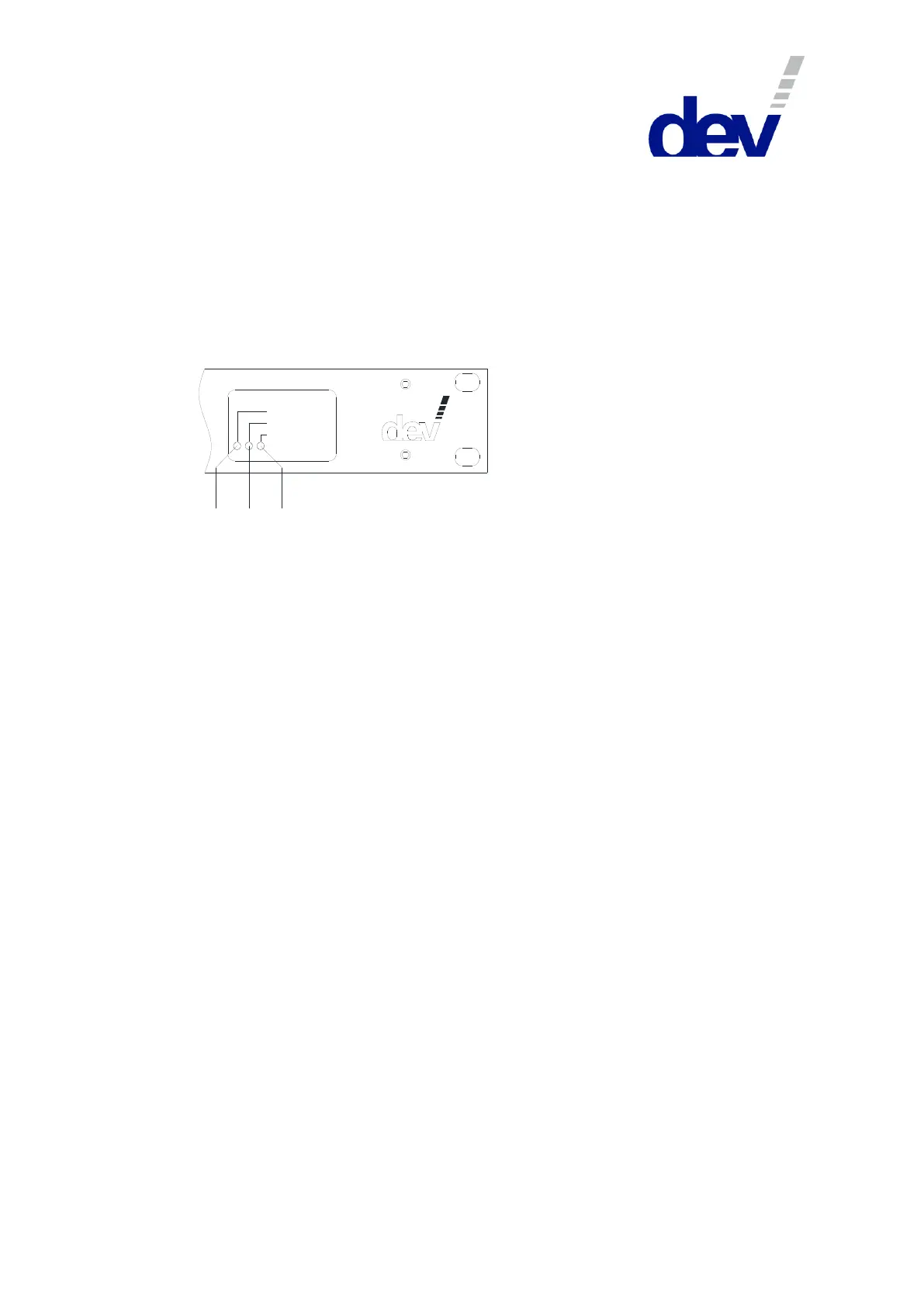
Three LEDs located at the device panel on the right are signalizing the power supply
operating status of the device:
Pow er S upply 1
Pow er S upply 2
Failure
8 9 10
"Power Supply 1" LED ((8), green) and "Power Supply 2" LED ((9), green):
The related power supply unit provides secondary voltage if this LED is on.
"Failure" LED ((10), red): This LED is on if either power supply unit does not
deliver any secondary voltage. The reason for this can be a defective power
supply, a defective primary protection fuse, or a missing primary voltage.
3.1.2 Communication Features
In addition to the device panel there are provided some options for the monitoring
and control of the product:
The standard digital interface of the DEV 1951 features basic remote switching
functionality permitting the control of the device, e.g. via a PLC (Programmable
Logic Control), please refer to chapter 5.4.
The Web Interface (chapter 5.5) provides features for checking the health status
and for changing the setup of the device; it enables full control in terms of
switching and in terms of setting up specific parameters. Additionally, the features
Time Based Switching and TRAC (if installed), and -for devices with installed sensing
switch modules- the recording functionality are accessible.
The implementation of SNMP (Simple Network Management Protocol) via the
Ethernet interface is intended to serve as the standard for remote monitoring and
control of the device (chapter 5.9).
In addition, a Communication Protocol Handler (CPH) is implemented which
enables the use of one of the following remote protocols with different monitoring
and control capabilities:
Sandar Prosan protocol via serial interface (chapter 5.6);
Leitch protocol via serial interface and via Ethernet interface (chapter 5.7); and
QEC protocol via serial interface and via Ethernet interface (chapter 5.8).
The installation of sensing switch modules and of digital signal switch modules
enables the autonomous switching capability (chapter 3.1.3) of the device based on
the signal quality. Moreover, the TRAC option (chapter 3.1.4) permits a remote
device to control the switching of the DEV 1951.