User Manual DEV 1951
Copyright DEV Systemtechnik GmbH 2004-2017 129
7 Connectors
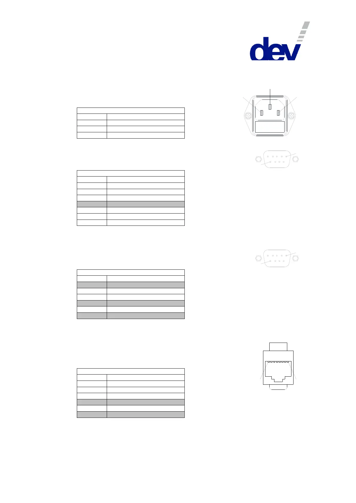
AC Power Plug
Connector: IEC rubber connector (male) IEC 60320 C14
Connector screws: none
Digital Interface Connector
Connector: Sub-D 9 (female)
Connector screws: UNC 4-40
Digital Interface Connector
Channel 2 Common pin (GND)
Channel 1 Common pin (GND)
• "do not use" means that normally the pin should be left open.
Serial Connector
Connector: Sub-D 9 (female)
Connector screws: UNC 4-40
Serial Connector (RS 232)
• "do not use" means that normally the pin should be left open. It is usually not a problem to use a fully
populated 1:1 Sub-D 9 (m)-(f) cable to establish a RS 232 connection between the device and a PC.
Ethernet Connector
Connector: RJ-45
Connector assembly: none
• "do not use" means that normally the pin should be left open.