User Manual DEV 1951
Copyright DEV Systemtechnik GmbH 2004-2017 25
4 Installation Instructions
4.1 Scope of Delivery
1 * DEV 1951 equipped with switch modules, distribution amplifier modules,
splitter modules, and other options,
as ordered
1 * User Manual (this document)
4.2 Installation of the Product
4.2.1 Mechanical Integration of the Product
Please refer to the warnings in chapter 2.3 regarding the mechanical integration of
the product. For the integration in a 19" rack, the rack slots must be prepared with
rails for the chassis. After inserting the chassis in the rack, fix the chassis with four
screws to the rack at its rack mount flanges.
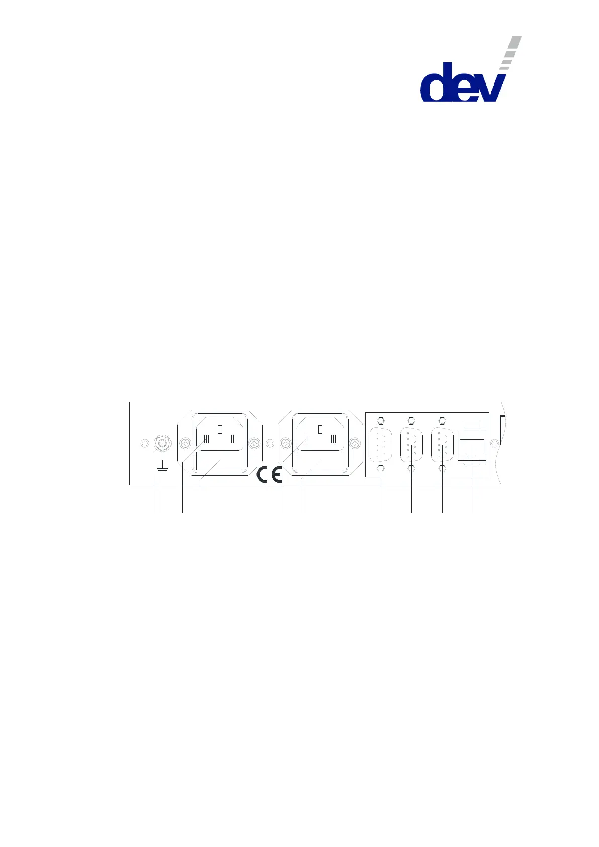
4.2.2 Grounding, Data Cables, Alarm Cable, and Power Connection
For the warnings with respect to "Grounding, AC Connection, Cables" please refer
to chapter 2.3.
The chassis needs to be connected to the 19" rack via a ground wire. The grounding
bolt is located on the left at the rear side of the product:
W ARNING:
Disconnect pow er
before opening!
1 2 3
4 5
6
7
8 9
Fuse 2 A T Fuse 2 A T
100...240 V
50...60 Hz
40 VA
Alarm
DIG/In RS 232
Ethernet
Take off the upper nut and the first washer of the grounding bolt (labeled 1 in the
figure above) and connect the grounding cable, which must have a ring tongue
terminal matching for the M4 fastening bolt. After that, the washer and the nut
have to be tightened again.
Next, establish the external Ethernet connection by plugging an Ethernet cable
from your network to the "Ethernet" port (9) of the device.
If the basic network setup via serial interface (chapter 4.4.2.2) is required, and/or if
it is intended to control the device via the serial interface using Sandar Prosan pro-
tocol, Leitch protocol, or QEC protocol, a serial connection between a PC and the
serial connector labeled "RS 232" (8) is to be established using a 1:1 cable. The
configuration of the serial interface is described in chapter 4.4.1.
If it is intended to control the DEV 1951 via the digital interface (chapter 5.4),
connect a prepared cable to the connector labeled "DIG/In" (7); the pin assignment
of the digital interface connector is stated in chapter 7.
If required, connect a prepared cable to the connector labeled "Alarm" (6); the pin
assignment of the alarm connector is subject of chapter 7 as well.