User Manual DEV 1951
Copyright DEV Systemtechnik GmbH 2004-2017 49
5.5.4.1 Switch
If a switch is selected on the left side of the Control Tab, the corresponding switch
panel appears on the right side. It consists of two or three sections:
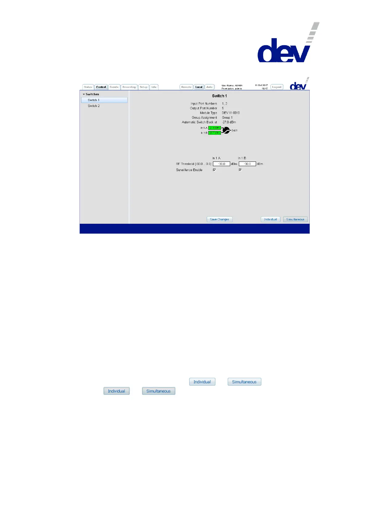
1) In the upper section below the descriptive designator (here: "Switch 1"), first the
"Input Port Numbers" and the "Output Port Number" of the switch module are shown as a
reference to the index of the SNMP .portTable (please refer to chapter 5.9.4.3.9)
and if port specific events are to be identified in the Events Tab (chapter 5.5.5).
Then the "Module Type" (here: "DEV 11-0010") and the "Group Assignment" -here always
"Group 1" since the group assignment of the DEV 1951 cannot be changed- are
listed. Additionally -with Option 28 (chapter 5.5.7.3.2) installed and acti-
vated- the line "Automatic Switch Back at" indicates the switch back level; here with
"-27.0 dBm" an offset (i.e. 3 dB) to the (standard -30 dBm) RF threshold level
setting is displayed.
2) Within the second section, the switching status of the switch module is shown
and can be changed.
Depending on the active switching mode, either the individual switching of the
current switch module can be performed, or the simultaneous switching of the
two switch modules. The switching mode is indicated at the lower right of any
switch panel by one of the buttons or being activated
(i.e. or ).
The screenshot above shows in the middle the measured RF level of each input
port on the left side. The green background implies that the RF level is above
the individual threshold, it is red otherwise.
The background color of a port rectangle appears in gray if the port is disabled
(e.g. by deactivating the corresponding "Surveillance Enable" check box), or if it does
not provide any status information.
The individual switching of a switch module is performed as follows:
To switch in Local Mode (!) only the selected module, Individual switching