User Manual DEV 1951
42 Copyright DEV Systemtechnik GmbH 2004-2017
Note:
The switching principle is that the pin of the channel/port to be switched is set
to the same electrical potential as the common pin.
Both common pins of the digital interface of the DEV 1951 (pin 8 and pin 2) are
on ground potential (GND). It is intended that the switching is performed via
(dry) relay contacts, but also open collector switching is possible if the voltage
of the open collector circuit does not exceed +12 V DC; TTL-level (+5 V DC) is
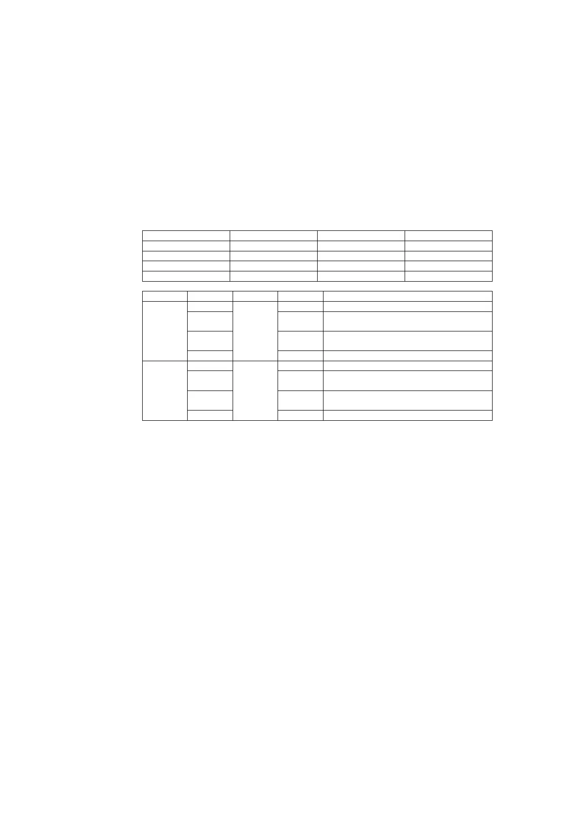
recommended. The following tables inform about the pin assignment on the
digital interface connector and about the behavior of the digital interface:
Individual: Channel 1 → "In A"
Simultaneous: both channels → "In A"
Individual: Channel 1 → "In B"
Simultaneous: both channels → "In B"
Individual: Channel 2 → "In A"
Simultaneous: (not functional)
Individual: Channel 2 → "In B"
Simultaneous: (not functional)
When switching the device to Remote Mode it is not guaranteed, that the
device is in the switching position(s) as given by the potentials of the contacts
of the digital interface.
Since switching via the digital interface is slope triggered, it is recommended to
generate a switching event after the activation of Remote Mode for any
channel in order to synchronize the device with the switching position(s) as
given by the potentials of the contacts of the digital interface. This event is
independent from the device being equipped with one or two switch modules
and the switching mode being Individual or Simultaneous.