EasyManua.ls Logo

Dickey-John gac 2100 blue User Manual

Dickey-John gac 2100 blue
87 pages
To Next Page IconTo Next Page
Page #1 background imageLoading...
Page #1 background image
GAC
®
2100 GRAIN
ANALYSIS COMPUTER
MODELS BLUE, GRAY, AND AGRI
Operator’s Manual
SINCE 1966
®

Table of Contents

Question and Answer IconNeed help?

Do you have a question about the Dickey-John gac 2100 blue and is the answer not in the manual?

Dickey-John gac 2100 blue Specifications

General IconGeneral
Grain Temperature CorrectionAutomatic
DisplayLCD
Dimensions12.5" H x 12.5" W x 15" D (31.75 cm H x 31.75 cm W x 38.1 cm D)
Moisture Range5 - 45% depending on grain
Temperature Range32-122°F (0-50°C)
Sample SizeApproximately 250 ml
Power Supply4 AA batteries or AC adapter

Summary

Safety Notices

Disclaimer

Legal statement regarding the manual's content and company rights.

Introduction

Accessories

List of optional and required accessories for the instrument.

Features

Specifications

Technical details including operating ranges and physical dimensions.

Access Codes

External Communication Connections

Details on connecting the instrument to external devices.

Printer

Unpacking the Instrument

Disengage Shipping Brace

Procedure to remove the shipping brace before operation.

Instrument Placement

GAC 2100 Dimensions

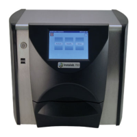
Physical dimensions of the GAC 2100 instrument.

To Level the Instrument

Leveling With Rubber Foot Pads

Detailed instructions on adjusting the instrument's foot pads.

Installation

Connecting AC Power

Instructions for connecting the instrument to a power source.

Sample Drawer Bypass

To Remove Sample Drawer Bottom

Steps to detach the bottom panel of the sample drawer.

Navigation

Display Screen and Contrast

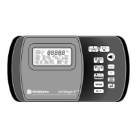
Description of the display and how to adjust its contrast.

Keyboard Layout

Explanation of the instrument's keyboard layout and functions.

Alarm and Key Functions

Navigation and Editing Keys

Functions of Backspace, Next Page, and Previous Page keys.

Action and Help Keys

Functions of Enter, Load, and Help keys.

Print and Unload Keys

Cursor and Navigation Keys

Menu Screens

Startup Procedure

Start Up Screens

Description of the initial language and self-check screens.

Test Samples (Quick Start)

Measure Moisture

Moisture Testing Preparation

Steps before commencing a moisture test.

Sample ID Number Entry

How to enter and use sample identification numbers.

Basic Method

Performing a Moisture Test

Core steps for conducting a moisture test.

Grain Sample ID Numbers

Entering Alphanumeric Data via Alpha Screen

Methods for entering alphanumeric data using the alpha screen.

ID Options

ID Options Configuration

Setting sample ID options like sequential, required, or optional entry.

Factors (Labels)

Blue Model Factors

Specifics for factors on the Blue model instrument.

Next Page View

Calculated D-Values and Blue Model Specifics

Definitions for D-values and Blue model specific data.

Grain Selection

Grain Calibration Storage

Information on how many grain calibrations are stored.

Selecting a Grain for Testing

Step-by-step guide to selecting a grain.

Quick Keys Menu

Blue Model Quick Keys

Specifics on programming Quick Keys for the Blue model.

Calibrate Procedures

View Calibration Data (1 Key)

Viewing and printing calibration constants for selected grains.

Enter/Change Calibration Values (2 Key)

Blue Model Calibration Changes

Restrictions and procedures for changing calibrations on the Blue model.

To Enter/Change Calibration Values

Print Calibration Grain List (3 Key)

To Print a Calibration List

Steps to generate and print the calibration list.

Obtain Basic Calibration Data (4 Key)

To Obtain Accurate Calibration Constants

Procedures for collecting calibration data.

Print Audit Memory Data (5 Key)

Blue Model Audit Memory Printing

Specifics for printing audit memory on the Blue model.

To Print the Audit Memory Contents

Steps to print audit memory data.

Memory Full (Blue Model)

After Printing Audit Memory

To Clear Audit Memory

Procedure for clearing the audit memory.

Instrument Setup

Clear Cycle Counter (1 Key)

Resetting the instrument's accumulated sample count.

To Reset the Cycle Counter

Steps to reset the cycle counter.

ID Options (2 Key)

ID Options Configuration

Setting sample ID options like sequential, required, or optional entry.

To Configure the ID Options

Steps to set up sample ID options.

Configure Output Options (3 Key)

Changing Output Options

Steps to modify output settings.

Instrument Security Button

Finding the security button needed for some configurations.

Settings

Change The Access Code (4 Key)

Blue Model Access Code

Access code functions specific to the Blue model.

To Change the Access Code

Change Date, Time, and Date Format (5 Key)

To Set the Time

Steps to set the current time on the instrument.

To Change the Date

To Change the Date Format

Change Labels (6 Key)

Label Types (User Name, Text Strings, Factor Names)

Details on editing user, text, and factor labels.

To Create Labels

Set Communications Port Parameters (7 Key)

Configuring Communications Ports

Steps to manage COM port settings.

To Configure COM Port Select

To Configure COM1 or COM2 Serial Data Setup

To Configure COM1 or COM2 Format

To Configure COM1 or COM2 Serial Data Setup

To Configure COM1 or COM2 Control Lead Setup

Quick Keys Menu

To Program a Quick Key

Steps to program Quick Keys.

Test Weight Bias Adjustment

To Change the Test Weight Bias

Steps to modify the test weight bias.

Test Weight Slope Adjustment

To Change the Test Weight Slope Adjustment

Steps to modify the test weight slope.

Moisture Bias Adjustment

To Change the Moisture Bias Adjustment

Steps to modify the moisture bias.

Locating the Instrument Security Button

Moisture Slope Adjustment

To Change the Moisture Slope Adjustment

Steps to modify the moisture slope.

Locating the Instrument Security Button

Finding the security button needed for some configurations.

Test Unit Performance

Non-Active Keys

Explanation of non-active selections.

View COM1 Port Configuration

Viewing COM1 port configuration and status.

To Access the COM1 Port

Steps to access COM1 port information.

View COM2 Transmit Port (3 Key)

To Configure the COM2 Transmit Port

Steps to configure COM2 transmit port.

View Display Characters (5 Key)

To Access Characters

Steps to view displayable characters.

View Diagnostic Mode (6 Key)

To Access Diagnostic Details

Steps to view detailed diagnostic information.

Test Network Mode (7 Key)

To Access the Test Network

Steps to enter the test network mode.

View/Print Parameters (8 Key)

To View the Parameters Menu

Steps to access the parameters menu.

Viewing Parameter Details

Accessing views for factory modes, serial number, constants, and counts.

Operator Maintenance

Cell Cleaning - Daily

Daily cleaning procedure for the grain cell.

Fuse Replacement

Steps for replacing a blown fuse.

Error Codes

Appendix A: Communication Ports

COM1 Port Options

Programmable options for the COM1 serial port.

COM1 Pin Assignment Details

Pin identification details for the COM1 port.

COM2 Pin Assignment Details

DICKEY-john® Warranty

Related product manuals