Digital Dream Standalone Motion Controller DDCS-Expert Users ManualPage-20
4.3 Spindle Wiring
4.3.1 Analog Spindle
Switch Power
Supply 1
Spindle Inputs
Spindle
COM-
COM+
DC24V
Wiring methods please
refers to OUTx Ports
Input and Output Power
Anolog
Circuit
(COM+/COM-)
DC-DC
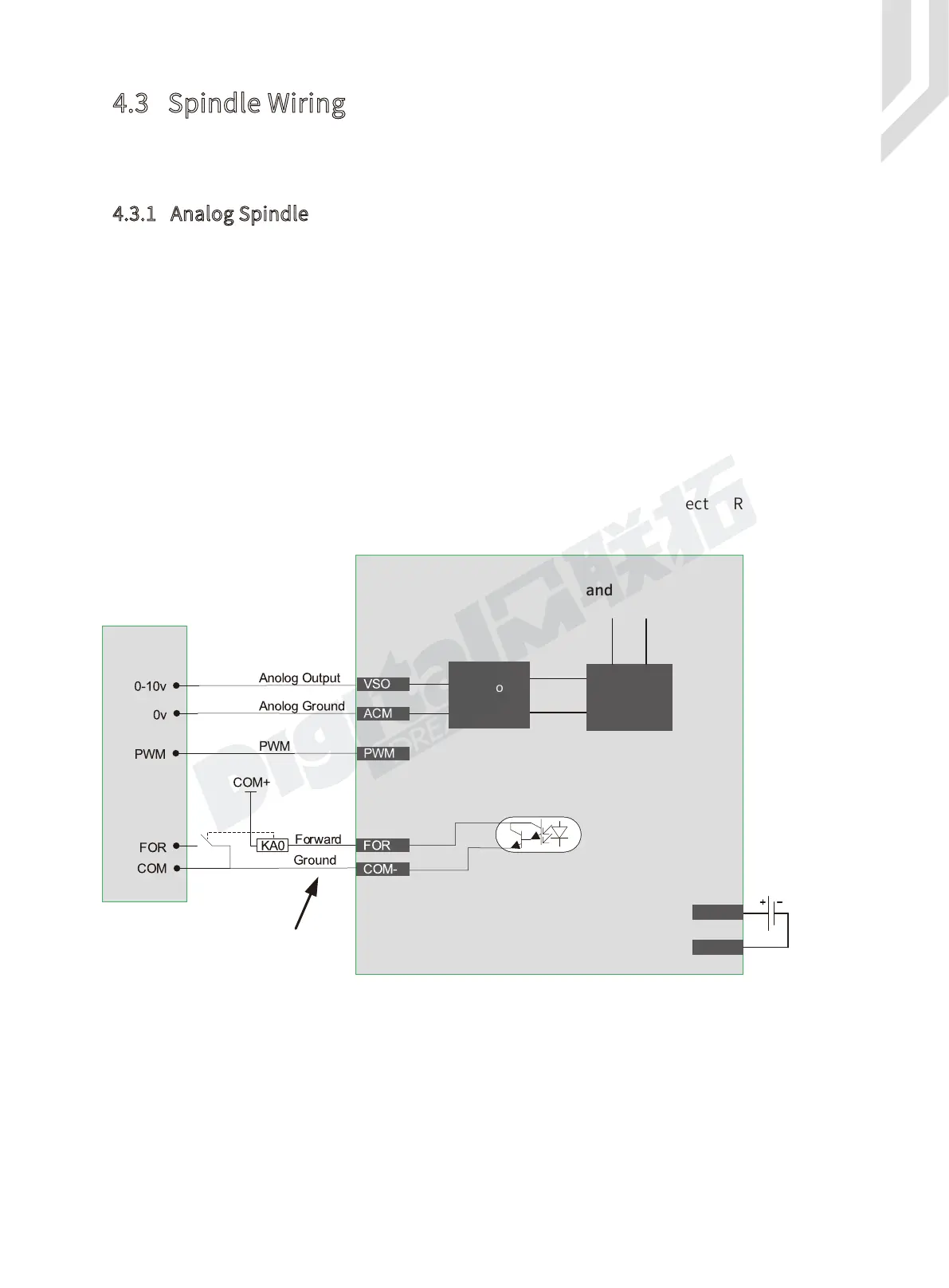
Figure 4-7 Spindle Wiring Methods
In Analog Spindle, the speed controlling output terminal can output 0-10V. It can adjust the
speed of the spindle motor by sending the voltage between 0 and 10V to the VFD according the
the Spindle Speed Setting.
Controlling the speed of a spindle with a VFD (variable frequency drive) only needs the Start
/ Stop signal and the 0-10V signal to control the frequency.
FOR port is same wiring methods as the normal Output Ports.
FOR is for spindle forward rotation output or start / stop output;
Analog circuit is isolated with Power supply output,Never short connect the ACM and COM-
( DCM );
If only need the Start and Stop command for the spindle, then just connect FOR output port
of the controller with Start input port of the inverter.
Important:
The “ VSO ” and “ PWM ” only one port is avaiable for one configuration. Use “ VSO ” port or
“ PWM ” port, the two ports cannot be used at the same time.
DDCS-Expert Support 3 kinds Spindle Mode: Analog Spindle / Servo Spindle (PUL+DIR) /
Multi-Speed Spindle. In the Param Page, by #079, we can define the spindle mode.