Digital Dream Standalone Motion Controller DDCS-Expert Users ManualPage-25
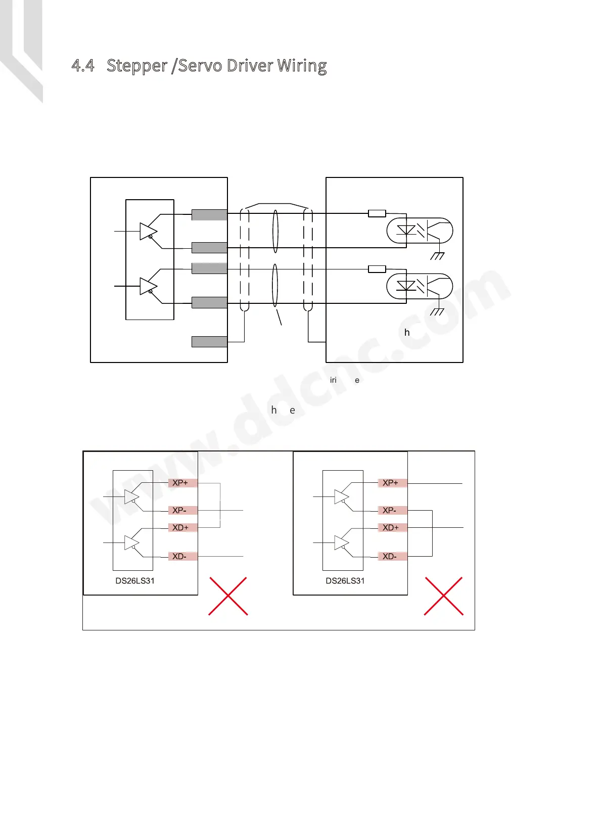
4.4 Stepper /Servo Driver Wiring
The stepper / servo control output, we cite differential Pulse and Direction output method
as Figure 1-12, Max. 1Mhz per axis. There is 3 or 4 or 5 axis for optional.
The Figure 1-12 we took X axis as the example, the Y, Z, A, B as the same wiring methods.
The Pulse and Direction signal output voltage is ± 5V.
Pulse+
Twist
Shielding
Cable
Pls use twist Shielding
cable for the connection
XP-
XD+
XD-
XP+
PE
Pulse-
Direction+
Direction-
Servo/Stepper
Driver
DS26LS31
Motion
Controller
Motion Controller Motion Controller
Pulse
Direction
Pulse
Direction
Common anode Common cathode
Figure 4-13 Pluse and direction signal wiring methods
Figure 4-14 Wrong wiring of pulse and direction
Common anode wiring or common cathode wiring, is not DDCS-EXPERT wiring methods.
The Figure 4-14 is the wrong wiring method.